This thread has been locked.

If you have a related question, please click the "Ask a related question" button in the top right corner. The newly created question will be automatically linked to this question.

CC1201EMK-868-930: GPIO Signal

Part Number: CC1201EMK-868-930
Other Parts Discussed in Thread: CC1201

Hi eveyOne

I control CC1201 by MCU, It works very well.

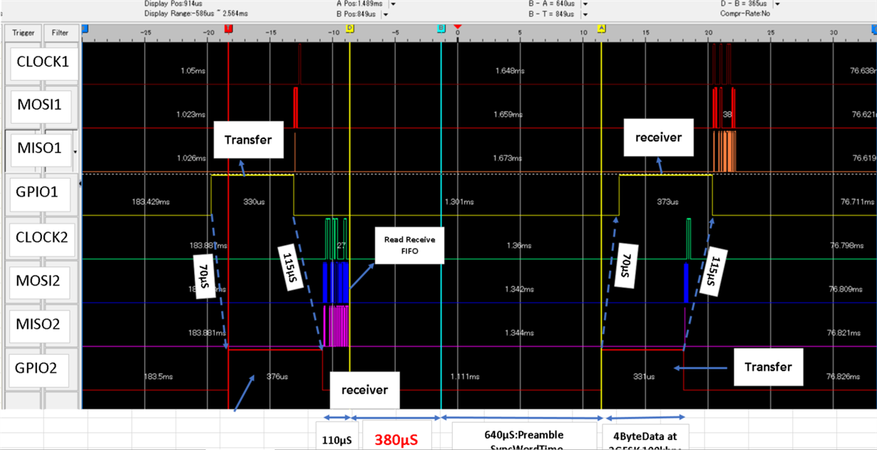
But i can not explain about the signal on GPIO, Pin0, Pin1.

I map Pin0 go up when received preamable/Synch words, go down when received all the payload data, i dont use CRC. 

The same with Pin1 for transfer data, go up when preamable/Synch words be sent, down when transfer complete.

I use 2 set (MCU + CC1201), tobe transfer and receiver.

One thing i can not understand, the time between  Pin1(of transfer set)go down and Pin0(of receiver set) go down is 115μs.(evnthough i put 2 set very near each other, 20 cm)

I incluced the picture i captured GPIO signal By Logic analyzer.

(On mypicture, Pin1 is GPIO1, Pin0 is GPIO2)

Anyone have explaination.

Thanks for your time. 

  • The signals are meant to indicate to the MCU that the radio is done receiving/transmitting and that it is safe to start the next instruction (TX, RX, PWD etc.) and are not a signal showing the exact timing of when the signal is on the air. Because of this there will be differences comparing Packet sent and packet received, even if the time it takes for the signal to be sent over the air can be ignored. Register settings will also play a role. If for example, append status is enabled, the status bytes will be but in the FIFO before the signal is de-asserted on the RX side.

    BR
    Siri