This thread has been locked.

If you have a related question, please click the "Ask a related question" button in the top right corner. The newly created question will be automatically linked to this question.

GDO pins configuration in SimpliciTI

Other Parts Discussed in Thread: SIMPLICITI, CC430F5137, CC1190, CC2500, CC1101, SN74AUP2G00, CC1100, MSP430F5529, CC1120

Hello

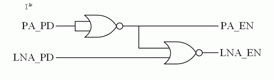
I'm a student working on my masters thesis related to low power wireless networks. I have a CC430F5137 mcu connected to a CC1190 and my intention is to control the PA using the GDO pins. In my case the GDO0 (P1.0)is connected to the PA_EN of the CC1190 and the GDO1 is connected to the LNA_EN of the CC1190. They should work in the fashion that the PA_EN goes high when sending (LNA low) and the opposit.  By default SimpliciTI seems to write the following radio registry values to the GDO ports (done in mrfi_radio.c):

/* GDO0 == PA_PD signal */
#define MRFI_SETTING_IOCFG0     27

/* GDO1 == RSSI_VALID signal */
#define MRFI_SETTING_IOCFG1     30

With these settings the PA works as I'd like it to, but inverted, that is it goes low while transmitting. What GDO1 does I don't really know...

The GDOs are configured with one byte each where the bits 0-5 defines the action, bit 6 inverts it and 7 is reserved.

I've activated the GDO pins using:

  P1SEL = 0x01;
  P3SEL = 0x40;

as dec(27) = bin(11011) I've tried to set bit 6 high -> bin(1011011) = dec(91) and write this to the GDO0 registry

#define MRFI_SETTING_IOCFG0     91      (this lines is used in the simpliciti code to write the values)

But this just leads to a disaster... When measuring the PA_EN pin with an oscilloscope it goes high a couple of random times and then dies.

Measuring the RF output it doesn't send anything whereas the same code with value 27 works fine, just doesn't activate the PA.

Changing the value of GDO1 to 28 for LNA action leads to a similar result where nothing works and the value of the pin is low.

I don't know what other parts of the code could be helpful, so please ask and I'll provide. One noteable thing is that if I control the GDO pins manually,

disabling the GDO periples, then the PA works just fine...But this isn't such a convinient way of using it and thereby I'd like to control it via the GDOs.

I'd greatly appreciate some help, I've been struggeling with this for two days and although some might not think it's much, my schedule is pushing me

and I'm running out of ideas... To my disposal I have a wide range of measuring equipments including regular oscilloscopes and spectroanalyzers,

so if there's anything that can be measured that could help, please mention it and I'll provide the data.

Thank you in advance. Best regards

Richard Salin


  • NOTE: See additional posts below for corrections to inconsistancies in this post.

    Richard,

    What you are trying to do is something that was never expected from SimpliciTI directly.  It is true there is some code (mainly for the RF front end parts like the CC1101 and CC2500) which could be turned on via a compiler switch and would toggle GPIO pins for managing a PA/LNA but as it turns out this code does not work entirely as expected either.  Unfortunately, I cannot give you an answer with specifies how to accomplish what you want with the CC430 only but I can tell you what is necessary to accomplish it overall.  I'll start with explaining some of what you are seeing.

    The CCA algorithm in SimpliciTI is implemented by taking advantage of the hardware in the CC1101 radio which allows one to transisition directly from an RX state to a TX state only if certain conditions are met.  SimpliciTI defines those conditions to be 1) we are not currently receiving a packet, and 2) the RSSI value is below a given threshold.  If these conditions are met at the time we strobe the radio state machine to go from the RX to TX state, then the radio makes the transition and begins transmitting the packet.  To detect whether ro not the radio succeeded in transmitting the packet, the IOCFG0 register is set to output the PA_PD signal (as you have noted) and the software watches for it to transition from high to low.  If it does, then the radio is asking a PA to no longer be powered down meaning the radio is currently transmitting.  If it doesn't go low then we are still in RX mode as we failed the CCA test and a retry is initiated.

    Thus, changing the active state of the signal will cause the code to invert its decisions with respect to it.  This is because the internal signal monitored in the RF1AIFG register is the same signal that is put out on the external I/O signal and your change has inverted them both, not simply the I/O signal.  This will confuse the code and you will not be able to transmit properly in a pretty short order, as you discovered.  It should be possible to go through the code and invert all of the decisions made on this signal if you really want to, but as you'll see later on, it won't provide you significant gain with respect to using a PA/LNA like the CC1190.

    The RSSI status signal is assigned to IOCFG1.  SimpliciTI monitors this signal to indicate when it is viable to read the RSSI register and also as an optimized timing mechanism for waiting to enter a CCA test.

    The RF_RDYn signal is assigned to IOCFG2 (intermittently within the mrfiRadioInterfaceCmdStrobe function).  This signal is monitored every time a command strobe is sent to the radio state machine to determine if the radio is in sleep state or not.  This is required as described in the CC430 users guide section 22.2.4.

    We are currently looking into the possibility of multiplexing the RSSI and RF_RDYn signals on IOCFG1 or IOCFG2 and allowing the other to be use as the LNA_PD signal but there is evidence that conflicts exist between operation of the baseline code and the receive ISR.  Thus, at this time, we cannot advise doing this with any confidence.

    Your statement that you have operated your system by manually toggling the PA_EN/LNA_EN signals via software with success is something I have difficulty believing.  Not that you didn't obtain successful operation with it, but rather that you didn't notice that the CCA algorithm was disabled by your actions.  We initially attempted this same style of implementation but found that the code simply doesn't have the resolution to know when to switch from LNA_EN to PA_EN in sync with the radio hardware.  Thus if you activeate the PA_EN signal before you call smplSend, then the CC1190 is already transmitting and the LNA side is disabled.  In this case, there is no way for the radio in the CC430 to monitor the actual radio energy and merely monitors the very quiet signal level of a disabled LNA output so CCA always succeeds.  Even if you move this signal transition deeper into the code at the point where we strobe the radio to move from RX to TX, you either invalidate the CCA as before or you delay turning on the PA which shortens the preamble length transmitted.  Neither solution is acceptable in our opinion.

    Thus, since we are stuck with only one signal in control of the radio hardware, we have to add some external logic to the system to achieve viable results with the CC1190/CC430 pair running SimpliciTI (at least in its current incarnation).  This is why it doesn't make sense to me to go through the trouble of correcting all the code decisions to allow inverting the PA_PD signal because we still have to put logic outside the system and using a NAND or AND gate really doesn't matter.

    The best suggestion I can give you right now is to use the IOCFG1/PA_PD signal (without inverting it so the code continues to work).  Define an I/O signal (i.e. LNA_PD) which will go high when we want the LNA disabled.  Set up the following external logic...

    Now, anytime you want the radio in receive or transmit mode, set the LNA_PD signal low otherwise set it high.  Yes, we want it active for transmissions as well because when the PA_PD signal goes active (low), it will disable the LNA and enable the PA at the appropriate time for the CCA test to be valid.  This has the additional benefit that it eliminates the possible invalid state where both the PA_EN and LNA_EN signals are high at the same time.  When the LNA_PD signal is set high and no active tranmission is ongoing, the PA/LNA will be completely disabled saving you power.

    I can understand this may not be the optimal choice for your implementation, but if you want to use SimpliciTI and not have to do a bunch of code modification at the lower levels, this is most likely your best option.

    I would suggest an SN74AUP2G00 little logic device (http://focus.ti.com/docs/prod/folders/print/sn74aup2g00.html) as it is low power and has several small package options.

    Regards,

    Jim

  • Jim, I am trying to solve the same thing. Looking at your solution, some things are not clear to me

    1. You wrote: The best suggestion I can give you right now is to use the IOCFG1/PA_PD

    While the default configuration is IOCFG0/PA_PD, is it a typo?

    2. Citation: This has the additional benefit that it eliminates the possible invalid state where both the PA_EN and LNA_EN signals are high at the same time

    but the logic on attached picture is not preventing this, as when PA_PD=low, then PA_EN=high, now toggling LNA_PD will give LNA_EN either high or low depending on LNA_PD. Am I missing something?

    3. The LNA_PD signal is not the LNA_PD signal that one can put onto GDO pins, but a signal that I'll create in my code, thus setting it "manually", right?

  • Adam,

    With regard to...

     1) Yes it is a typo and it should have been IOCFG0/PA_PD.

    2) The logic diagram is incorrect.  I failed to swap the logic operator when I applied Demorgans theorem.  The intended logic was to prioritize on the PA_EN state so CCA would work.  Here is the correct truth table, Karnaugh maps, and Boolean algebra

    and here is the corrected logic diagram

    The correct part would be SN74AUP2G02 located here http://focus.ti.com/docs/prod/folders/print/sn74aup2g02.html

    3) Correct.  The "manually" statement intends for you to manage this signal within software via your own code.  The simplest and most portable mechanism (with respect to updating the SimpliciTI code) would be to create small, possibly inline, wrapper functions which apply the change of state for the LNA_PD signal, call the intended function, and restore the state of the LNA_PD signal.

    Thanks for keeping me honest!

    Regards,

    Jim

  • As I do not need to save power, I implemented simple invertor on PA_PD to create PA_EN and used PA_PD directly as LNA_EN. This solution works.

    I also implemented my own switching thru two port signals in routines MRFI_RxModeOn and MRFI_RxModeOff creating both LNA_EN and PA_EN "manually". They give signals slightly sooner than internal PA_PD, but this works too.  I am using external CC1190 kit and 38.4kBaud rate in SimpliciTI in one AP to one ED communication. It could be I am cutting of with this solution the CCA, but for 2 device communication this works.

  • Adam,

    I agree the simple inverter solution works assuming the power budget is not a concern.  Also creating the two signals from within the software also works, and quite well for a two radio system.  In general, many radio systems really don't requrie a CCA algorithm from a lab environment point of view.  However, it is important to recognize even a two radio system still needs to exist in an environment where other radio systems can exist and the software only solution effectively disables the CCA operation.  Under FCC guidlines, this is allowed and there are many systems which do not use CCA by design.  Under ETSI, CCA (or its equivalent) is required for certain systems.

    I'm not trying to tell you what you must do to get things to work, rather I'm merely pointing out that a "working" solution doesn't necessarily guarantee operation in a deployed environment and it also doesn't guarantee operation within a given regions regulatory requirements.  For demonstration purposes, the software solution may be great but if you are required to generate a producable design, this system may not pass testing for a given region without additional components, i.e. the inverter as a minimum.

    All in all, glad to hear you are making progress!

    Regards,

    Jim

  • Hello,

    I have a similar problem. I designed one board with a CC430F5137 and a CC1190 amplifier.

    I choosed for the CC1190:

    GDO0 - PA_EN

    GDO1 - LNA_EN

    GDO2 - HGM

    To begin with, I control these signals as GPIOs and later on I will set then as GDOs.

    Well, now as a GPIO, it turns out that simpliciTI uses GDO1 as RRSI indicator and PA_PD for GDO1:

    /* GDO0 == PA_PD signal */
    #define MRFI_SETTING_IOCFG0     27 

    /* GDO1 == RSSI_VALID signal */
    #define MRFI_SETTING_IOCFG1     30

    How can I modify simpliciTI so that it does not change any GDO outputs ?

    Regards,

    Jorge

  • Hi Jorge


    I would suggest that you take a look at the simpliciTI code for CC1100/CC1101. This is the same radio as the CC430 but it is not a SoC. The CC1101 does not have the possibility to output the RSSI_VALID signal on a GDO pin so it only uses GDO0 and changes between the following configurations:


    /* GDO functionality */
    #define MRFI_GDO_SYNC      6
    #define MRFI_GDO_CCA        9
    #define MRFI_GDO_PA_PD    27  /* low when transmit is active, low during sleep */
    #define MRFI_GDO_LNA_PD  28  /* low when receive is active, low during sleep */


    If you rewrite your code to be similar as the CC1101 code you have two available GDO lines that you can use: GDO1, and GDO2. 
    One of the signals you need (HGM) must be controlled from a GPIO.

    BR

    Siri

  • Hello Siri,

    Many thanks for your quick answer.

    To begin with, I would like to control the signals as GPIOs instead of outputing GDOs interrupts (although I am aware it is not the best solution).

    How can I program that outputs to be GPIOs ?

    On table Table 25-21 from CC430 user guide there are many configuration, all of them as GDOs outputs.

    From now on, I just want to program those outputs as GPIOs so that I can control if they are HIGH or LOW.

    Regards,

    Jorge.

  • Hi

    You cannot output these signals on GPIOs. If you are using GPIOs you simply has to configure some GPIOs manually to be outputs and then you need to set these outputs in the same way as the radio would set the LNA_PD and PA_PD signals. The PA_PD signal is low in TX and high in any other states. The LNA_PD is low in RX and high in all other states. This means that in your code you must set these signals before strobing STX/SRX and after exiting these modes.

    BR

    Siri

  • Yes, I have the code to control my amplifier with GPIOS. No problem with that. It is much easier.

    The problem is that I routed the GDO signals to my amplifier and I do not know how to control them as GPIOs

    Is it posible to use the GDOs as GPIOs? I thought it was posible but I do not find which register I have to write to do so.

    I hope I dont have to re-route my PCB.

    Many thanks in advance.

    Jorge

  • According to the data sheet,

    GDO2 is routed to P1.1,

    GDO0 to P1.0, and

    GDO1 to P3.6.

    By setting IOCFG2 = 0x1B, GDO2 is output on P1.1 and will behave as the PA_PD.

    I assume that PxSEL must be set to 1 for the GPIOs (P1.0, P1.1, and P3.6).

    BR

    Siri

  • Hi ,

      I'm still a bit confused about the definition of GDO pins. I am using CC1120 with MSP430F5529 and neither of these datasheets have the term GDO in them. Are the GDO pins just GPIO pins on the microcontroller that we should make sure are physically connected to the radio pins with the signals PA_PD, RSSI status, and RF_RDYn signals? And then make sure to connect the appropriate IOCFG with those GPIO pins?

    Thanks for any clarification. 

  • I think I've figured out looking at the schematic of the radio (CC1120) and the fact that GDO1 is shared with an SPI pin.
    So GDO0 is actually called GPIO0 on CC1120,
    GDO1 is called GPIO1 (which is shared with SO for SPI)
    GDO2 is called GPIO2

    I am using a booster pack to connect the radio EM to a Launchpad (MSP430F5529) so on this boosterpack,
    the radio's GPIO0 is called GPIOA
    and GPIO2 is called GPIOB

    Which when following the physical connection on to the launchpad we see that
    GPIOA(aka GPIO0, aka GDO0) is connected to P2.0 on LP, and
    GPIOB (aka GPIO2, aka GDO2) is connected to P6.5 on LP!!

    Phew!