This thread has been locked.

If you have a related question, please click the "Ask a related question" button in the top right corner. The newly created question will be automatically linked to this question.

CC1310: Output of Binary data signal that comes from the demodulator when receiving in OOK mode

Part Number: CC1310
Other Parts Discussed in Thread: CC1350, CC1020

Hi, 

Q1. When we use partial queue for reading data from FIFO is it possible to obtain  RSSI value as following:

    rfc_propRxOutput_t      rxStatistics;

    RF_cmdPropRx.pOutput = (UInt8*)&rxStatistics;

    Sorry, but I didn't check it yet by myself.

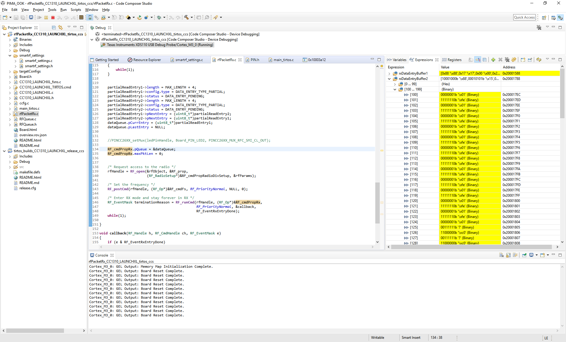
Q2. Accordance to the data obtained from FIFO it looks that for 2500 bps Symbol Rate we see 12 samples.

0638.DataExcel.xlsx

     Can we change it?

BR Leonid

  • Hi Leonid

    Please share the settings (API command and overrides) you are using, and also info about what data you are actually transmitting and we can take a look at this. I have never tested the transparent FIFO mode so I will have to make a small example here and want to know what settings your are using.

    BR

    Siri
  • Hi Siri,

    thanks for answer.

    Some Note:

    1. We use signal generator to transmit 2500 bps OOK wave (400 mcs - 0, 400 mcs - 1).

    2. Rf was configured to output received data to FIFO (OUTPUT_2_FIFO=1) - see pOverrides_ook.

    3. Rf was configured to work in OOK mode with symbol rate 200 mcs (.symbolRate.rateWord = 131).

        With that setting we receive clear signal when data was outputted to pin (OUTPUT_2_FIFO=0)

    Here  the code:


    #include <xdc/std.h> #include <xdc/runtime/System.h> /* BIOS Header files */ #include <ti/sysbios/BIOS.h> /* TI-RTOS Header files */ #include <ti/drivers/rf/RF.h> #include "smartrf_settings.h" #include "smartrf_settings_predefined.h" /***** Defines *****/ static void callback(RF_Handle h, RF_CmdHandle ch, RF_EventMask e); //TI temporary undocumented definitions #define IOC_PORT_RFC_SMI_CL_OUT (0x37) #define PINCC26XX_MUX_RFC_SMI_CL_OUT IOC_PORT_RFC_SMI_CL_OUT #define DEFINE_LED_FOR_DEMODULATOR_ACTIVITY_MONITORING_SUPPORT(IOID_xx) TPort::setMux(IOID_xx, PINCC26XX_MUX_RFC_SMI_CL_OUT) //temporary RF definitions static RF_Object rfObject; static RF_Handle rfHandle; static RF_CmdHandle rxCmdHndl = NULL; /* Handle needed to abort the RX command */ #define ENTRY_LEN (1000) //2. Configure two partial read buffers for the received data. Make sure that the buffers are 4 byte aligned. #define PARTIAL_RX_ENTRY_HEADER_SIZE 12 #if defined(__IAR_SYSTEMS_ICC__) #pragma data_alignment = 4 static uint8_t rxDataEntryBuf1[PARTIAL_RX_ENTRY_HEADER_SIZE + ENTRY_LEN]; #pragma data_alignment = 4 static uint8_t rxDataEntryBuf2[PARTIAL_RX_ENTRY_HEADER_SIZE + ENTRY_LEN]; #endif static dataQueue_t dataQueue; static uint8_t* packetDataPointer; rfc_dataEntryPartial_t* partialReadEntry1 = (rfc_dataEntryPartial_t*)&rxDataEntryBuf1; rfc_dataEntryPartial_t* partialReadEntry2 = (rfc_dataEntryPartial_t*)&rxDataEntryBuf2; rfc_dataEntryPartial_t* currentReadEntry = (rfc_dataEntryPartial_t*)&rxDataEntryBuf1; rfc_propRxOutput_t rxStatistics_prop; /* Output structure for CMD_PROP_RX */ void TTestAddonMonitor::entry() { //congigure RF in Rx mode OOK and output data to pin and FIFO RF_Params rfParams; DEFINE_LED_FOR_DEMODULATOR_ACTIVITY_MONITORING_SUPPORT(ANALOG_GPIO_1); RF_Params_init(&rfParams); partialReadEntry1->length = (ENTRY_LEN) + 4; partialReadEntry1->config.type = DATA_ENTRY_TYPE_PARTIAL; partialReadEntry1->status = DATA_ENTRY_PENDING; partialReadEntry2->length = (ENTRY_LEN) + 4; partialReadEntry2->config.type = DATA_ENTRY_TYPE_PARTIAL; partialReadEntry2->status = DATA_ENTRY_PENDING; partialReadEntry1->pNextEntry = (uint8_t*)partialReadEntry2; partialReadEntry2->pNextEntry = (uint8_t*)partialReadEntry1; dataQueue.pCurrEntry = (uint8_t*)partialReadEntry1; dataQueue.pLastEntry = NULL; /* Modify CMD_PROP_RX command for application needs */ RF_cmdPropRx.pQueue = &dataQueue; /* Set the Data Entity queue for received data */ RF_cmdPropRx.maxPktLen = 0; //must be set to 0 for unlimited packet length RF_pCmdPropRadioDivSetup_ook->centerFreq = 0x01B2; RF_pCmdPropRadioDivSetup_ook->loDivider = 0xa; rfHandle = RF_open(&rfObject, RF_pProp_ook, (RF_RadioSetup*)RF_pCmdPropRadioDivSetup_ook, &rfParams); RF_pCmdFs_preDef->frequency = 0x01b1; RF_pCmdFs_preDef->fractFreq = 0xEB85; RF_runCmd(rfHandle, (RF_Op*)RF_pCmdFs_preDef, RF_PriorityNormal, NULL, 0); rxCmdHndl = RF_postCmd(rfHandle, (RF_Op*)&RF_cmdPropRx, RF_PriorityNormal, &callback, IRQ_RX_ENTRY_DONE /*RF_EventRxEntryDone*/); while(1) { //wait for event, .... } } #define NUMBER_OF_BUFFERS 5 #define DATA_BUFFER_LENGTH (ENTRY_LEN*NUMBER_OF_BUFFERS) static uint8_t data[DATA_BUFFER_LENGTH]; static uint16_t index = 0; void callback(RF_Handle h, RF_CmdHandle ch, RF_EventMask e) { if (e & RF_EventRxEntryDone) { // Get a pointer to the first IQ sample byte packetDataPointer = &currentReadEntry->rxData; //--------------------------------------------------------------------------- memcpy(&data[index], packetDataPointer,ENTRY_LEN); index += ENTRY_LEN; if (index >= (DATA_BUFFER_LENGTH)) { index = 0; } currentReadEntry->status = DATA_ENTRY_PENDING; currentReadEntry = (rfc_dataEntryPartial_t*)currentReadEntry->pNextEntry; } }

    Here the settings:

    // TI-RTOS RF Mode Object
    RF_Mode RF_prop_ook =
    {
        .rfMode = RF_MODE_PROPRIETARY_SUB_1,
        .cpePatchFxn = &rf_patch_cpe_genook,
    
        .mcePatchFxn = &rf_patch_mce_genook,
    
        .rfePatchFxn = &rf_patch_rfe_genook,
    };
    
    // Overrides for CMD_PROP_RADIO_DIV_SETUP OOK
    uint32_t pOverrides_ook[] =
    {
        // override_use_patch_prop_genook_nrz.xml
        // PHY: Use MCE RAM patch, RFE RAM patch
        //MCE_RFE_OVERRIDE(1,0,0,1,0,0),
    	
    	/*
    If you need to “sniff” the transmitter to find out what it is sending you should output the raw data on the RX side. 
    To do this in OOK mode, you need to change the MCE_RFE override to
    // Mode 2: Transparent data from bit slicer to pin (no synchronization/tracking)
    MCE_RFE_OVERRIDE(1,0,2,1,0,0) 	
    	*/
    #if(OUTPUT_2_FIFO)
    MCE_RFE_OVERRIDE(1,0,3,1,0,0),	
    #else	
    MCE_RFE_OVERRIDE(1,0,2,1,0,0),
    #endif
    
        // override_synth_prop_863_930_div5.xml
        // Synth: Set recommended RTRIM to 7
        HW_REG_OVERRIDE(0x4038,0x0037),
        // Synth: Set Fref to 4 MHz
        (uint32_t)0x000684A3,
        // Synth: Configure fine calibration setting
        HW_REG_OVERRIDE(0x4020,0x7F00),
        // Synth: Configure fine calibration setting
        HW_REG_OVERRIDE(0x4064,0x0040),
        // Synth: Configure fine calibration setting
        (uint32_t)0xB1070503,
        // Synth: Configure fine calibration setting
        (uint32_t)0x05330523,
        // Synth: Set loop bandwidth after lock to 20 kHz
        (uint32_t)0x0A480583,
        // Synth: Set loop bandwidth after lock to 20 kHz
        (uint32_t)0x7AB80603,
        // Synth: Configure VCO LDO (in ADI1, set VCOLDOCFG=0x9F to use voltage input reference)
        ADI_REG_OVERRIDE(1,4,0x9F),
        // Synth: Configure synth LDO (in ADI1, set SLDOCTL0.COMP_CAP=1)
        ADI_HALFREG_OVERRIDE(1,7,0x4,0x4),
        // Synth: Use 24 MHz XOSC as synth clock, enable extra PLL filtering
        (uint32_t)0x02010403,
        // Synth: Configure extra PLL filtering
        (uint32_t)0x00108463,
        // Synth: Increase synth programming timeout (0x04B0 RAT ticks = 300 us)
        (uint32_t)0x04B00243,
        // override_phy_rx_aaf_bw_0xd.xml
        // Rx: Set anti-aliasing filter bandwidth to 0xD (in ADI0, set IFAMPCTL3[7:4]=0xD)
        ADI_HALFREG_OVERRIDE(0,61,0xF,0xD),
        
    	// override_phy_agc_reflevel_0x19.xml
        // Rx: Set AGC reference level to 0x19
        //HW_REG_OVERRIDE(0x6088,0x0019),
    	//HW_REG_OVERRIDE(0x6088,0x0012),	
    	HW_REG_OVERRIDE(0x6088,0x0024),	
    	
        // override_phy_ook_rx.xml
        // Rx: Set LNA bias current trim offset to 3
        (uint32_t)0x00038883,
        // Rx: Freeze RSSI on sync found event
        HW_REG_OVERRIDE(0x6084,0x35F1),
        // override_phy_ook_tx_symbol_4_8kbaud.xml
        // Tx: Set symbol duty-cycle delay before symbol ramp-down to 0x78 (=120). This means symbol ramp down will begin after reaching (T_symbol/2) plus wait a delay of (120/2)=60 us.
        HW_REG_OVERRIDE(0x52B8,0x8078),
        // override_phy_ook_rx_filter_iir_k_1div4.xml
        // Rx: Set data filter to IIR, k=1/4. Explanation: 0x0000: k=1 (no filter), 0x0001: k=1/2, 0x0002: k=1/4, 0x0003: k=1/8.
        HW_REG_OVERRIDE(0x5204,0x0002),
    		
    	// override_phy_ook_tx_power_max.xml
        // Tx: Ramp symbol shape to maximum PA level (0x7200). Explanation: min power=0x6100, ..., max power=0x7200. Bits [15:13] sets wait delay per PA ramp level. Bits[12:8] sets number of PA levels to use from ramp LUT (range 1-18). Bits[7:0] reserved.
        HW_REG_OVERRIDE(0x6098,0x7200),
        // override_phy_rx_rssi_offset_5db.xml
        // Rx: Set RSSI offset to adjust reported RSSI by +5 dB
        (uint32_t)0x00FB88A3,
    
    	HW_REG_OVERRIDE(0x1110, RFC_DBELL_SYSGPOCTL_GPOCTL0_MCEGPO0| //MCE_GPO0	Binary data signal that goes to the modulator when sending.
                                RFC_DBELL_SYSGPOCTL_GPOCTL1_MCEGPO1| //MCE_GPO1	Binary data signal that comes from the demodulator when receiving. 
                                RFC_DBELL_SYSGPOCTL_GPOCTL2_CPEGPO0| //CPE_GPO0 Controls an external LNA front-end. High when the LNA must be enabled, otherwise low 
                                RFC_DBELL_SYSGPOCTL_GPOCTL3_RATGPO0  //RAT_GPO0	Goes high when a transmission is initiated and low when the transmission is done. Can be used for accurate timing synchronization.
                       ),
    
    	/***********************************band definitions, added, not changed*******/
    	// override_synth_disable_bias_div10.xml
        // Synth: Set divider bias to disabled
        HW32_ARRAY_OVERRIDE(0x405C,1),
        // Synth: Set divider bias to disabled (specific for loDivider=10)
        (uint32_t)0x18000280,	
    	
    #if(IQ_PATCH_ACTIVE)			
    	// Set to avoid internal FIFO overflow when running the IQ Dump Patch
    	(uint32_t)0x001082C3,
    #endif	
    	
    		
        /***********************************end of band********************************/	
    
    	(uint32_t)0xFFFFFFFF,
    };
    
    // CMD_PROP_RADIO_DIV_SETUP OOK
    rfc_CMD_PROP_RADIO_DIV_SETUP_t RF_cmdPropRadioDivSetup_ook =
    {
        .commandNo = 0x3807,
        .status = 0x0000,
        .pNextOp = 0, // INSERT APPLICABLE POINTER: (uint8_t*)&xxx
        .startTime = 0x00000000,
        .startTrigger.triggerType = 0x0,
        .startTrigger.bEnaCmd = 0x0,
        .startTrigger.triggerNo = 0x0,
        .startTrigger.pastTrig = 0x0,
        .condition.rule = 0x1,
        .condition.nSkip = 0x0,
        .modulation.modType = 0x2,
        .modulation.deviation = 0x0,
        .symbolRate.preScale = 0xF,
        //.symbolRate.rateWord = 0xC4A,
    	//.symbolRate.rateWord = 0x666,//2500
    	//.symbolRate.rateWord = 786, //1200
    //.symbolRate.rateWord = 546,	       //833
    	//.symbolRate.rateWord = 1666,	   //1091
    	//.symbolRate.rateWord = 666,	   //1000
    	//.symbolRate.rateWord = 524,	   //800
        //.symbolRate.rateWord = 262,      //400
    	.symbolRate.rateWord = 131,        //200   ok!!!
    	//.rxBw = 0x20,
    	.rxBw = 41,
    	
    	.preamConf.nPreamBytes = 0x4,
        .formatConf.nSwBits = 0x20,
        .formatConf.bBitReversal = 0x0,
    #if(IQ_PATCH_ACTIVE)
    //When using the patch some changes have to be done to the API exported from SmartRF Studio.
    //formatConf.bMsbFirst in CMD_PROP_RADIO_DIV_SETUP must be set to 0 to allow for LSB to be
    //transmitted first	
    	
    	.formatConf.bMsbFirst = 0x0,	
    #else	
        .formatConf.bMsbFirst = 0x1,
    #endif	
        .formatConf.fecMode = 0x0,
        //.formatConf.whitenMode = 0x1,
    	.formatConf.whitenMode = 0x0,
        .config.frontEndMode = 0x0,
        .config.biasMode = 0x1,
    	.config.analogCfgMode = 0x0,
        .config.bNoFsPowerUp = 0x0,
        .txPower = 0xA73F,
        .pRegOverride = pOverrides_ook,
        .centerFreq = 0x0364,
        .intFreq = 0x8000,
        .loDivider = 0x05,
    };
    
    // CMD_FS
    rfc_CMD_FS_t RF_cmdFs_preDef =
    {
        .commandNo = 0x0803,
        .status = 0x0000,
        .pNextOp = 0, // INSERT APPLICABLE POINTER: (uint8_t*)&xxx
        .startTime = 0x00000000,
        .startTrigger.triggerType = 0x0,
        .startTrigger.bEnaCmd = 0x0,
        .startTrigger.triggerNo = 0x0,
        .startTrigger.pastTrig = 0x0,
        .condition.rule = 0x1,
        .condition.nSkip = 0x0,
        .frequency = 0x0364,
        .fractFreq = 0x0000,
        .synthConf.bTxMode = 0x0,
        .synthConf.refFreq = 0x0,
        .__dummy0 = 0x00,
        .__dummy1 = 0x00,
        .__dummy2 = 0x00,
        .__dummy3 = 0x0000,
    };
    

    BR

    Leonid

  • Hi Leonid

    I will do some testing on the lab on Monday, because from home I am not able to get any data that makes sense from the data entries.
    However, I am wondering about the data rate you are programming. You say that you use a data rate of 2.5 kbps, but you program the data rate to 200 bps and you are sending a preamble at 2.5 bps
    What exactly are you showing in your excel sheet. Do you read 12 bytes from the data entries that are 255 and 12 bytes that are 0?

    BR

    Siri
  • Hi Leonid

    I have been able to do some testing today. what I did was to use the 4.8 kbps settings from Studio (I tested on 868 MHz) and then I change the data rate to 2.5 kbps.On the TX side, I sent a continuous preamble at 2.5 kbps.

    I change the following override:

    HW_REG_OVERRIDE(0x5204,0x0002)

    to:

    HW_REG_OVERRIDE(0x5204,0x0102)

    When looking at the data I received in the data entry, I received 8 bits of 1's for every 1 and 0 bits of 0's for every 0:

    Siri

  • Hi Siri,

    Before output the data to FIFO we try to output data to the pin. 

    The bit rate was set to 200 bps to prevent from  AGC to receive the noise.

    Actual data was sent with 2500 bps and WITHOUT preamble and sync.

    When we start tests with FIFO the setting remain the same. But data from signal generator was of various form as following for  example:

    400 mcs - 0/400 mcs - 1,

    800 mcs - 0/400 mcs -1

    2800 mcs -0/ 400 mcs -1

    and etc.

    We saw appropriate data in the FIFO.

    And yes we have 0 and 255 data in FIFO.

    BR

    Leonid


  • hi Leonid

    did my override give you what you wanted? It will give you 8 bits in the Data entry for every bit received (data rate programmed for 2.5 kbps).

    Siri
  • Hi Siri,
    Thanks for answer.
    In smartrf_settings.c we see the following:
    // override_phy_ook_rx_filter_iir_k_1div4.xml
    // Rx: Set data filter to IIR, k=1/4. Explanation: 0x0000: k=1 (no filter), 0x0001: k=1/2, 0x0002: k=1/4, 0x0003: k=1/8.
    HW_REG_OVERRIDE(0x5204,0x0002),
    Q: what is the meaning of the HW_REG_OVERRIDE(0x5204,0x0102) override?
    BR
    Leonid
  • Hi leonid

    When using transparent mode to FIFO, bit 15:8 in register 0x40045204 gives the ability to control how often we will sample the magnitude and write data to pin in transparent mode.

    0: no transparent downsample
    1: transparent downsample by two
    2: transparent downsample by four
    3: transparent downsample by eight
    4: transparent downsample by sixteen

    bit 7:0 in the same register:

    The magnitude from the magnitude estimator can optionally we low pass filtered through an IIR filter before being compared to the bit slicer threshold. The BW is controlled through this register:
    0: no filter
    1: k=1/2
    2: k=1/4
    3: k=1/8

    BR
    Siri
  • Hi Siri,

    I use the LaunchPad with cc1350, what is the Override command to change the External Signal? i need to use MCE_GPO1 on DIO_1 pin.

    Also how can i use Override from the code? has any example of this?

    thanks,

  • Please see:

    on how to route RF Core Signals to Physical Pins.

    Not sure I understand you second questions.

    The overrides needs to be configured through the setup command. You should not change any registers in any other ways.

    BR

    Siri

  • Hi Siri,

    Thanks for the answer.

    I work on new  board that designed to include the cc1350 and  need to communicate with old board which including cc1020 and work in following RF configuration:

    System parameters:
    X-tal frequency: 14.745600 MHz Internal
    X-tal accuracy: +/- 3 ppm
    RF frequency A: 915.000000 MHz Active Rx
    RF frequency B: 915.000000 MHz Inactive Tx
    Frequency separation: 16.200 kHz
    Data rate: 9.600 kBaud
    Data Format: UART Accurate
    RF output power: 5 dBm
    Channel width: 100 kHz
    Modulation: FSK Dithering enabled
    Lock: Continuous
    Carrier sense offset: 0 dBm DCLK squelch disabled
    Operator Mode: Rx.

    For now i work with one CC1350 LaunchPad and try with Smart RF Studio to receive data from the old board but i not get any data.

    My old board work with proprietary protocol so i not sure if the problem is the packet form or something in RF parameters.

    So i try to get MCE_GPO1 (Binary data signal that comes from the demodulator when receiving) in RFC_GPO0 and connect RFC_GPO0 to DIO_1.

    I use the example with some changes:

    // Map RAT_GPO2 to RFC_GPO0
    // Map MCE_GPO1 to RFC_GPO1
    //HWREG(RFC_DBELL_BASE + RFC_DBELL_O_SYSGPOCTL) = RFC_DBELL_SYSGPOCTL_GPOCTL0_RATGPO2 | RFC_DBELL_SYSGPOCTL_GPOCTL1_MCEGPO1;

    so i send:  HW_REG_OVERRIDE(0x1020,0x005E) from override editor in Smart RF Studio and change the DIO1 to connect RF core data out 0, but i not get data on DIO_1.

    I try also to send:  HW_REG_OVERRIDE(0x1110,0x005E)  but i not get data on DIO_1.

    Q1: is i do the override correct?

    Q2: do you have any recommendation how to continue?

    Q3: I add photo of my LaunchPad maybe some jumper is not in the place?

  • Hi

    I tend to forget that when using the OOK patch there is another method for outputting the signals (ignore what is in the user's guide). Sorry about that. If you want the OOK signal out on a pin instead of in a data entry, you need to change mode by setting

    MCE_RFE_OVERRIDE(1,0,2,1,0,0)

    To getting the OOK signal out on IOID_1 you need to add the following:

    PIN_Config pinTable[] =
    {
    IOID_1 | PIN_GPIO_OUTPUT_EN | PIN_GPIO_LOW | PIN_PUSHPULL | PIN_DRVSTR_MAX,
    PIN_TERMINATE
    };
    .
    .
    PINCC26XX_setMux(pinHandle, IOID_1, PINCC26XX_MUX_RFC_SMI_CL_OUT);
    

    Siri

  • Hi Siri,

    thanks again,

    The problem is that i not use OOK but i use FSK modulation.

    Is this mode work when using FSK also?

  • No. When using fsk you need to use the method described in the user guide I referred to. I just took the rfPacketRX example in our SDK and modified it to output the received serial data on IOID_1:

    In smartrf_setting.c I added:

    #include DeviceFamily_constructPath(inc/hw_rfc_dbell.h)
    .
    .
    .
    // Overrides for CMD_PROP_RADIO_DIV_SETUP
    static uint32_t pOverrides[] =
    {
        // override_use_patch_prop_genfsk.xml
        // PHY: Use MCE ROM bank 4, RFE RAM patch
        MCE_RFE_OVERRIDE(0,4,0,1,0,0),
        .
        .
        .
        .
        HW_REG_OVERRIDE(0x1110, RFC_DBELL_SYSGPOCTL_GPOCTL1_MCEGPO1),
        (uint32_t)0xFFFFFFFF,
    };

    and in rfPacketRX.c:

    #include <ti/drivers/pin/PINCC26XX.h>
    .
    .
    .
    PIN_Config pinTable[] =
    {
        Board_PIN_LED2 | PIN_GPIO_OUTPUT_EN | PIN_GPIO_LOW | PIN_PUSHPULL | PIN_DRVSTR_MAX,
    #if defined Board_CC1352R1_LAUNCHXL
        Board_DIO30_RFSW | PIN_GPIO_OUTPUT_EN | PIN_GPIO_HIGH | PIN_PUSHPULL | PIN_DRVSTR_MAX,
    #endif
        IOID_1 | PIN_GPIO_OUTPUT_EN | PIN_GPIO_LOW | PIN_PUSHPULL | PIN_DRVSTR_MAX,
        PIN_TERMINATE
    };
    
    void *mainThread(void *arg0)
    {
        RF_Params rfParams;
        RF_Params_init(&rfParams);
    
        /* Open LED pins */
        ledPinHandle = PIN_open(&ledPinState, pinTable);
        if (ledPinHandle == NULL)
        {
            while(1);
        }
    
        if( RFQueue_defineQueue(&dataQueue,
                                rxDataEntryBuffer,
                                sizeof(rxDataEntryBuffer),
                                NUM_DATA_ENTRIES,
                                MAX_LENGTH + NUM_APPENDED_BYTES))
        {
            /* Failed to allocate space for all data entries */
            while(1);
        }
    
        /* Modify CMD_PROP_RX command for application needs */
        /* Set the Data Entity queue for received data */
        RF_cmdPropRx.pQueue = &dataQueue;           
        /* Discard ignored packets from Rx queue */
        RF_cmdPropRx.rxConf.bAutoFlushIgnored = 1;  
        /* Discard packets with CRC error from Rx queue */
        RF_cmdPropRx.rxConf.bAutoFlushCrcErr = 1;   
        /* Implement packet length filtering to avoid PROP_ERROR_RXBUF */
        RF_cmdPropRx.maxPktLen = MAX_LENGTH;        
        RF_cmdPropRx.pktConf.bRepeatOk = 1;
        RF_cmdPropRx.pktConf.bRepeatNok = 1;
    
        PINCC26XX_setMux(ledPinHandle, IOID_1, PINCC26XX_MUX_RFC_GPO1);
        .
        .
    

    BR

    Siri

  • Hi Siri,

    You write:

    Hi leonid

    When using transparent mode to FIFO, bit 15:8 in register 0x40045204 gives the ability to control how often we will sample the magnitude and write data to pin in transparent mode.

    0: no transparent downsample
    1: transparent downsample by two
    2: transparent downsample by four
    3: transparent downsample by eight
    4: transparent downsample by sixteen

    bit 7:0 in the same register:

    The magnitude from the magnitude estimator can optionally we low pass filtered through an IIR filter before being compared to the bit slicer threshold. The BW is controlled through this register:
    0: no filter
    1: k=1/2
    2: k=1/4
    3: k=1/8

    BR
    Siri
    */
    HW_REG_OVERRIDE(0x5204,0x0102), //we see 6 samples per bit, siri - 8

    Q1: Is it right that  bit 15:8 is set to 0 we have  12 samples ?

    Q2: is it possible to change this value(for bit 15:8 equal to 0)?

    BR

    Leonid

  • Hi Leonid

    I think that how many samples you will get will (for a given override) will depend on the RX BW and the data rate you are using.

    Can you please give us the complete list of RF settings you are using? Is it correct that what you are trying to schieve is transparent mode to FIFO with 8 bits oversampling?

    The override I gave you when getting 8 bits was with a data rate of 2.5 kbps.

    For thesettings you are using, does everything look OK if you are just using transparent to pin? I am not sure how hight we can go in data rate with the OOK patch, and I know that the settings in STudio is optimized for 4.8 kbps and that the duty cycle will not longer be 50 % if you change the data rate a lot.

    Siri
  • Hi Siri, here the RF settings:

    // CMD_PROP_RADIO_DIV_SETUP OOK
    rfc_CMD_PROP_RADIO_DIV_SETUP_t RF_cmdPropRadioDivSetup_ook =
    {
        .commandNo = 0x3807,
        .status = 0x0000,
        .pNextOp = 0, // INSERT APPLICABLE POINTER: (uint8_t*)&xxx
        .startTime = 0x00000000,
        .startTrigger.triggerType = 0x0,
        .startTrigger.bEnaCmd = 0x0,
        .startTrigger.triggerNo = 0x0,
        .startTrigger.pastTrig = 0x0,
        .condition.rule = 0x1,
        .condition.nSkip = 0x0,
        .modulation.modType = 0x2,
        .modulation.deviation = 0x0,
        .symbolRate.preScale = 0xF,
        .symbolRate.rateWord = 131,        //200   ok!!!
        .rxBw = 41,                      //+- 150Khz  , sensitivity -110dB
    	
        .preamConf.nPreamBytes = 0x4,
        .formatConf.nSwBits = 0x20,
        .formatConf.bBitReversal = 0x0,
    #if(IQ_PATCH_ACTIVE)
    //When using the patch some changes have to be done to the API exported from SmartRF Studio.
    //formatConf.bMsbFirst in CMD_PROP_RADIO_DIV_SETUP must be set to 0 to allow for LSB to be
    //transmitted first	
    	
        .formatConf.bMsbFirst = 0x0,	
    #else	
        .formatConf.bMsbFirst = 0x1,
    #endif	
        .formatConf.fecMode = 0x0,
        .formatConf.whitenMode = 0x0,
        .config.frontEndMode = 0x0,
        .config.biasMode = 0x1,
        .config.analogCfgMode = 0x0,
        .config.bNoFsPowerUp = 0x0,
        .txPower = 0xA73F,
        .pRegOverride = pOverrides_ook,
        .centerFreq = 0x01B2,
        .intFreq    = 0x8000,
        .loDivider  = 0xa;,
    };
    // Overrides for CMD_PROP_RADIO_DIV_SETUP OOK
    uint32_t pOverrides_ook[] =
    {
        // override_use_patch_prop_genook_nrz.xml
        // PHY: Use MCE RAM patch, RFE RAM patch
        //MCE_RFE_OVERRIDE(1,0,0,1,0,0),
    	
    	/*
    If you need to “sniff” the transmitter to find out what it is sending you should output the raw data on the RX side. 
    To do this in OOK mode, you need to change the MCE_RFE override to
    // Mode 2: Transparent data from bit slicer to pin (no synchronization/tracking)
    MCE_RFE_OVERRIDE(1,0,2,1,0,0) 	
    	*/
    
    MCE_RFE_OVERRIDE(1,0,3,1,0,0),	
    
        // override_synth_prop_863_930_div5.xml
        // Synth: Set recommended RTRIM to 7
        HW_REG_OVERRIDE(0x4038,0x0037),
        // Synth: Set Fref to 4 MHz
        (uint32_t)0x000684A3,
        // Synth: Configure fine calibration setting
        HW_REG_OVERRIDE(0x4020,0x7F00),
        // Synth: Configure fine calibration setting
        HW_REG_OVERRIDE(0x4064,0x0040),
        // Synth: Configure fine calibration setting
        (uint32_t)0xB1070503,
        // Synth: Configure fine calibration setting
        (uint32_t)0x05330523,
        // Synth: Set loop bandwidth after lock to 20 kHz
        (uint32_t)0x0A480583,
        // Synth: Set loop bandwidth after lock to 20 kHz
        (uint32_t)0x7AB80603,
        // Synth: Configure VCO LDO (in ADI1, set VCOLDOCFG=0x9F to use voltage input reference)
        ADI_REG_OVERRIDE(1,4,0x9F),
        // Synth: Configure synth LDO (in ADI1, set SLDOCTL0.COMP_CAP=1)
        ADI_HALFREG_OVERRIDE(1,7,0x4,0x4),
        // Synth: Use 24 MHz XOSC as synth clock, enable extra PLL filtering
        (uint32_t)0x02010403,
        // Synth: Configure extra PLL filtering
        (uint32_t)0x00108463,
        // Synth: Increase synth programming timeout (0x04B0 RAT ticks = 300 us)
        (uint32_t)0x04B00243,
        // override_phy_rx_aaf_bw_0xd.xml
        // Rx: Set anti-aliasing filter bandwidth to 0xD (in ADI0, set IFAMPCTL3[7:4]=0xD)
        ADI_HALFREG_OVERRIDE(0,61,0xF,0xD),
    	
        // override_phy_ook_rx.xml
        // Rx: Set LNA bias current trim offset to 3
        (uint32_t)0x00038883,
    	
        // override_phy_rx_rssi_offset_5db.xml
        // Rx: Set RSSI offset to adjust reported RSSI by +5 dB
        (uint32_t)0x00FB88A3,
    	
    /*********************start of specific part***********************************/    
        	    
    /********************* debug definitions     ***********************************/    	
    #if(RF_DEBUG_MODE)
    /*    
    Interrupt on SYNCWORD
    When it comes to getting the sync found signal out on a pin, they should add the following to the override list:
        */
    // Output sync found signal on RATGPO1
        (uint32_t)0x008F88B3,
    	SW_REG_BYTE_OVERRIDE(frontEndPar, gpoControl, 0x8F),	
    
    	HW_REG_OVERRIDE(0x1110, RFC_DBELL_SYSGPOCTL_GPOCTL0_MCEGPO0| //MCE_GPO0	Binary data signal that goes to the modulator when sending.
                                RFC_DBELL_SYSGPOCTL_GPOCTL1_MCEGPO1| //MCE_GPO1	Binary data signal that comes from the demodulator when receiving. 
    							RFC_DBELL_SYSGPOCTL_GPOCTL2_RATGPO1| //The signal RATGPO1 may be configured to go high when sync is found in the receiver, and low when the packet is received or reception aborted 	
                                //RFC_DBELL_SYSGPOCTL_GPOCTL2_CPEGPO0| //CPE_GPO0 Controls an external LNA front-end. High when the LNA must be enabled, otherwise low 
                                RFC_DBELL_SYSGPOCTL_GPOCTL3_RATGPO0  //RAT_GPO0	Goes high when a transmission is initiated and low when the transmission is done. Can be used for accurate timing synchronization.
                       ),
    #endif
    /*********************end of debug definitions ********************************/    		
    
    /***********************************band definitions, added, not changed*******/
    	// override_synth_disable_bias_div10.xml
        // Synth: Set divider bias to disabled
        HW32_ARRAY_OVERRIDE(0x405C,1),
        // Synth: Set divider bias to disabled (specific for loDivider=10)
        (uint32_t)0x18000280,	
    /***********************************end of band********************************/	
    
    /**********************************	Diversity definitions Tx/Rx, removed in Rx ST3***/
        // Rx: Freeze RSSI on sync found event
        HW_REG_OVERRIDE(0x6084,0x35F1),
        // override_phy_gfsk_pa_ramp_agc_reflevel_0x1a.xml
        // Tx: Enable PA ramping (0x41). Rx: Set AGC reference level to 0x1A.
        HW_REG_OVERRIDE(0x6088,0x411A),
        // Tx: Configure PA ramping setting
        HW_REG_OVERRIDE(0x608C,0x8213),
    	
    /**********************************	End of Diversity **************************/	


    /**********************************	Tx Power definitions, added, changed*******/
        // TX power override
        // Tx: Set PA trim to max (in ADI0, set PACTL0=0xF8)
        ADI_REG_OVERRIDE(0,12,0xF8),
    /***********************************end of band Tx Power **********************/		
    /********************* OOK definitions      ***********************************/      	    
        // override_phy_agc_reflevel_0x19.xml        //tbd!!!
        // Rx: Set AGC reference level to 0x19
    	HW_REG_OVERRIDE(0x6088,0x0024),	
    	
        // Rx: Freeze RSSI on sync found event
        HW_REG_OVERRIDE(0x6084,0x35F1),
    
        // override_phy_ook_tx_symbol_4_8kbaud.xml
        // Tx: Set symbol duty-cycle delay before symbol ramp-down to 0x78 (=120). This means symbol ramp down will begin 
             after reaching (T_symbol/2) plus wait a delay of (120/2)=60 us.
        HW_REG_OVERRIDE(0x52B8,0x8078),
    
        // override_phy_ook_rx_filter_iir_k_1div4.xml
        // Rx: Set data filter to IIR, k=1/4. Explanation: 0x0000: k=1 (no filter), 0x0001: k=1/2, 0x0002: k=1/4, 0x0003: k=1/8.
    /*
    Hi leonid
    
    When using transparent mode to FIFO, bit 15:8 in register 0x40045204 gives the ability to control how often we will sample the magnitude and write data to pin in transparent mode.
    
    0: no transparent downsample 
    1: transparent downsample by two 
    2: transparent downsample by four 
    3: transparent downsample by eight 
    4: transparent downsample by sixteen 
    
    bit 7:0 in the same register:
    
    The magnitude from the magnitude estimator can optionally we low pass filtered through an IIR filter before being compared to the bit slicer threshold. The BW is controlled through this register: 
    0: no filter 
    1: k=1/2 
    2: k=1/4 
    3: k=1/8 
    
    BR
    Siri	
    */	
        HW_REG_OVERRIDE(0x5204,0x0102),       //we see  6 samples per bit, siri - 8
       
    	// override_phy_ook_tx_power_max.xml
        // Tx: Ramp symbol shape to maximum PA level (0x7200). Explanation: min power=0x6100, ..., max power=0x7200. Bits [15:13] sets wait delay per PA ramp level. Bits[12:8] sets number of PA levels to use from ramp LUT (range 1-18). Bits[7:0] reserved.
        HW_REG_OVERRIDE(0x6098,0x7200),
    /********************* end of OOK definitions***********************************/      	    
    	
    		
    /*********************end of specific part*************************************/    
    
    	(uint32_t)0xFFFFFFFF,
    };
    BR
    Leonid


  • Hi Leonid

    As far as I can see you are trying to set a data rate of 200 bps and an RX BW of 311 kHz. This is not supported. Please use SmartRF Studio and OOK settings there, and you will see how Symbol rate and RX BW can be configured. The lowest data rate you can have, is 1.9 kbps.

    BR

    Siri