This thread has been locked.

If you have a related question, please click the "Ask a related question" button in the top right corner. The newly created question will be automatically linked to this question.

CC1352P: How does "Matched Filter Balun" (swra629) work with CC1352P?

Part Number: CC1352P
Other Parts Discussed in Thread: CC1352R

Hi CC Team,

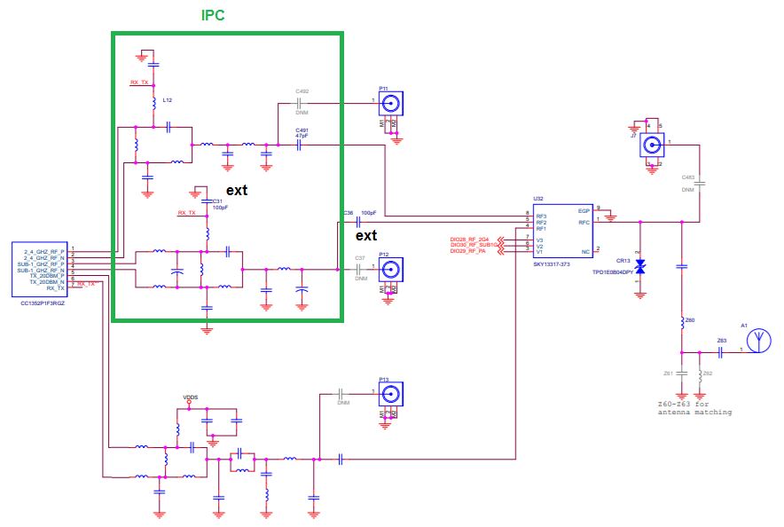
I just stumbled across the document "Matched Filter Balun for CC1352 and CC1352P" which describes a new Integrated Passive Component (IPC) which is said to be available (or at least coming) from Johanson Technology and Murata. As a current user of other Johanson Technology integrated baluns for several other CC family processors, we are obviously keen to evaluate. 

I have some questions regarding the document:

  • The reference designs look excellent for use of the IPC with the CC1352R. However, despite the document saying "The CC1352 IPC can be used for both CC1352R and CC1352P" it is not obvious how the extra high power PA port on the CC1352P would be connected. The IPC only shows two RF "channels". 
  • Unfortunately there is not yet any information for the new IPC on either JTI's or Murata's websites. Can you provide Part Numbers or other reference or contact info I can use to track down prototype and production parts?

Thanks for your assistance

  • Hi,

    The IPC (shown in green) can be used for the low power section only in CC1352P. Refer to figure below.

    The part numbers have unfortunately been omitted from the released version but this will be fixed shortly.

    • Murata Part Nr: LFB21868MDZ5E757
    • Johanson Technology (JTI) Part Nr: 0900PC15A0036

    Regards, Richard

  • Hi Richard

    Thanks for the extra information. I would suggest the recommended solution for the CC1352P should be specifically addressed in the swra629 application note.

    • Is there any plan to produce an IPC balun for either the PA high-power channel alone of the CC1352P, or better still a full three-channel IPC for the P?
    • In the meantime, when designing a circuit for the CC1352P, for the TX20DBM channel would you recommend using the balun circuit and component values from the LAUNCHXL-CC1352P1 reference design?

    • The reference design for the CC1352R and IPC balun shows RX_TX (pin 5 of the processor) and external cap C41 connected to pin 5 of the balun. The recommended layout for the RX_TX signal is easy. However, with the CC1352P the two TX_20DBM signals are on pins 5 and 6, and RX_TX is on pin 7. Are there any critical pcb layout issues for RX_TX such as track width, length or layer? Can it cross under the TX_20DBM_x signals on another PCB layer?

    Thanks

    Rob

  • Hi Rob,

    I will update the information in the app note so it will be more clear.

    There are no current plans to make an IPC device for the PA high power section. This is a joint decision with Johanson or Murata and TI if there is a need for the part. A three-channel IPC would be too large so the cost would increase.

    For the Tx 20 dBm channel, recommend to copy the design from the LAUNCH-CC1352P1 ref design. I would use the same passive size (0201), position of each component and routing if possible. Otherwise, the component values might need to be tweeked if the layout changes too much.

    RxTx track: Keep layer-2 a solid GND plane and the RxTx track can be routed on layer 3. When routed on layer-3, then it can cross the 20 dBm signals since layer-2 is GND. The width and length of RxTx tracks are not too sensitive but try to copy the ref design as much as possible.

    Regards, Richard
  • Thanks Richard. Will follow your advice.

    I'll mark this resolved, but leave a request on the table for a IPC device for the PA high power section. A solution using the CC1352P is otherwise so easy that it's a shame to require 0201 components in just this section.

    Thanks again.

    Rob