This thread has been locked.

If you have a related question, please click the "Ask a related question" button in the top right corner. The newly created question will be automatically linked to this question.

CC120XEM-868-930-RD: About arrangement of Saw Filter and LNA

Part Number: CC120XEM-868-930-RD

Hi All,

The customer is asking questions about Post's comments below.

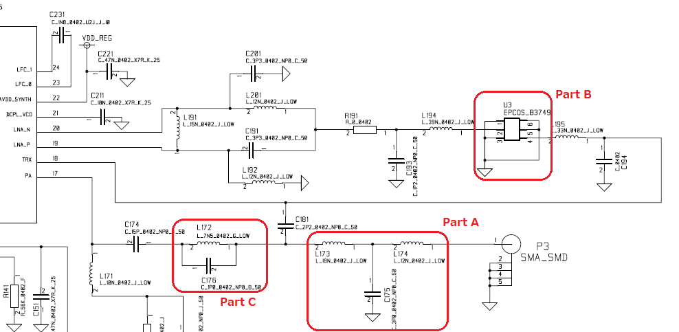
The figure below is a circuit diagram of the antenna part of CC1125EM_Cat1_schematic.pdf in the article.

1. Is it correct to replace part A with SAW filter?

2. Is it correct to replace part B with LNA?

3. Should I delete the filter of part C?

Best Regards,

Takashi

  • Could you please give some context to the questions?

    It is not clear why they want to move the SAW filter, if they want to use the chip with an external LNA, PA or similar etc.
  • Hi TER-san,

    Thank you for your quick response.
    I will check with the customer so please wait.

    Best Regards,
    Takashi
  • Hi TER-san,

    Customer is verifying the waveform with a spectrum analyzer from the SMA connector on the CC1200EMK.

    However, because there was no margin for near spurious, I was asked about inserting a SAW filter.

    "CC1125EM-CAT1-868RD" is introduced for the use of the SAW Filter, but the customer thinks that it is better to have the SAW filter in the part A in the circuit diagram.

    Will the spurious be improved by placing a SAW filter at point A and an LNA at point B?

    Best Regards,

    Takashi

  • "However, because there was no margin for near spurious, I was asked about inserting a SAW filter.": Which frequencies do they have spurious on?

    If they want to remove spurious in TX they have to place the SAW filter in the 'A' position.