This thread has been locked.

If you have a related question, please click the "Ask a related question" button in the top right corner. The newly created question will be automatically linked to this question.

RTOS/LAUNCHXL-CC1312R1: SPI Mode Confusion

Part Number: LAUNCHXL-CC1312R1
Other Parts Discussed in Thread: CC1312R, CC1310

Tool/software: TI-RTOS

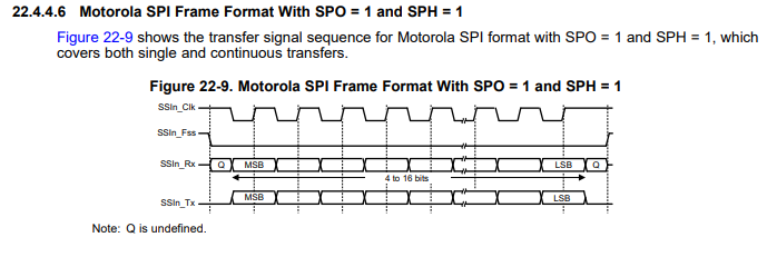
I have my SPI master set to mode 0 which I have verified on my scope. The CC1310 and now the CC1312R both only work if i set SPI_POL1_PHA1 which is mode 3. Have Ti got their modes mixed?

  • Andrew,

    The CC1310 and CC1312R's SPI protocol works differently when using single transfer vs. continuous transfer. Please see the CC1310 or CC1312 TRM's SSI chapter. 

    BR,

    Seong

  • Thanks for the reply. I see that the SPI module single transfer is slightly different to continuous transfer, but this doesn't change the mode of SPI. Looking at SWCU185C TRM it seems that the difference is only in the chip select pin SSIn_FSS. I am not using this pin at all and it is set to PIN_UNASSIGNED. 

    Do I need to use SSIn_FSS as normally in SPI this is not necessary with only one slave connected to the master?

    Thanks,

    Andy

  • I have a CC1310 Launchpad and have slave SPI working okay. I have a CC1312R launchpad with exactly the same slave SPI configuration and for reason when the slave transmits its data the first byte is defaultTxBufValue. Why is this?

  • Andrew,

    Which frameformat are you using? There are three programmable interface oeprations for Motorola SPI, MICROWIRE, or TI SSIs. This is set with SPI_Params.frameFormat.

    defaultTxBufValue is a scratch buffer used with the UDMA controller. Is this how you're configuring your CC1310 and CC1312?

    Are you writing your code based on the SPI example code from the latest SDK?

    BR,

    Seong

  • Hi Seong,

    Thanks for your help with this. So a little more information:

    1) Yes, I am using SPI. The odd thing is that the master device (currently a Raspberry Pi used for testing) is set to SPI mode 0 and verified on a scope. The CC1312R is set to SPI_POL1_PHA1 which is SPI mode 3. This configuration actually works on the CC1310 whereas no other configuration does. However, the same configuration for the CC1312R only works from master to slave because the slave, the CC1312R, produces an empty byte at the start of its packet when transmitting. This extra byte is defaultTxBufValue.

    2) I have tried setting minDmaTransferSize=1, and minDmaTransferSize=10000. My understanding is that if minDmaTransferSize is set to a number larger than transaction.count of the SPI then the uDMA will not be used. Nothing here makes any difference.

    3) I am moving from the CC1310 as I ran out of RAM, but I have started afresh using the CC1312R example projects. Everything is the very latest versions and the collector example was used as a base project.

    simplelink_cc13x2_26x2_sdk_3_10_01_11

    IAR 8.40.1

    From the TRM I see that the first byte is loaded when SSIn_FSS goes low. Do I have to do this manually because I am not using chip select? Instead I am using my own pin interrupt which calls SPI_transfer() and SPI_transferCancel() so that I have a hardware way of resetting the SPI interface.

    Regards,

    Andy

  • *update*

    I have this working now but only by bringing in the driver files and modifying them. Essentially I have enabled the csn interrupt and partial return, and am not using my own pin interrupt. I have added a callback to the csn ISR so that the SPI is set again ready for a transfer. Only by enabling the csn in the SPI am I able to eliminate the unwanted byte at the start of the slave tx.

    Here is the modified csn ISR:

    static void csnCallback(PIN_Handle handle, PIN_Id pinId)
    {
        uintptr_t            key;
        SPICC26X2DMA_Object *object;
        SPI_Handle           spiHandle;
    
        spiHandle = (SPI_Handle) PIN_getUserArg(handle);
        object = spiHandle->object;
    
        /* Transfer started if CSN low */
        if (!PIN_getInputValue(object->csnPin)) {
            key = HwiP_disable();
    
            if (object->headPtr != NULL) {
                /* Indicate transaction started */
                object->headPtr->status = SPI_TRANSFER_STARTED;
            }
            else {
                /* Disable all interrupts */
                PIN_setInterrupt(handle, object->csnPin);
                object->returnPartial = SPICC26X2DMA_retPartEnabledIntNotSet;
    
    #warning might need to add callback here too to start a new SPI_transfer
    
            }
    
            HwiP_restore(key);
        }
    
        /* Cancel transfer if CSN high */
        if (PIN_getInputValue(object->csnPin)) {
            key = HwiP_disable();
    
            /* Disable all interrupts */
            PIN_setInterrupt(handle, object->csnPin);
            object->returnPartial = SPICC26X2DMA_retPartEnabledIntNotSet;
    
            /* Indicate why the transaction completed */
            if (object->headPtr != NULL) {
                object->headPtr->status = SPI_TRANSFER_CSN_DEASSERT;
            }
    
            HwiP_restore(key);
    
            /* Cancel the current transaction */
            SPICC26X2DMA_transferCancel(spiHandle);
            
    #warning testing: code added here for hardware based SPI callback 
            /* Perform callback */
            SPI_Transaction transaction;
            transaction.status = SPI_HARDWARE_CSN_DEASSERT;
            object->transferCallbackFxn(spiHandle, &transaction);
    
        }
    }

    Then added a new enumeration value in SPI.h:

    typedef enum {
        SPI_TRANSFER_COMPLETED = 0,      /*!< SPI transfer completed */
        SPI_TRANSFER_STARTED,            /*!< SPI transfer started and in progress */
        SPI_TRANSFER_CANCELED,           /*!< SPI transfer was canceled */
        SPI_TRANSFER_FAILED,             /*!< SPI transfer failed */
        SPI_TRANSFER_CSN_DEASSERT,       /*!< SPI chip select was de-asserted (only
                                              applicable in return partial mode) */
        SPI_TRANSFER_PEND_CSN_ASSERT,    /*!< SPI transfer is pending until the chip
                                              select is asserted */
        SPI_TRANSFER_QUEUED,              /*!< SPI transfer added to transaction queue */
          
        SPI_HARDWARE_CSN_DEASSERT
    } SPI_Status;

    Then in callback:

        case SPI_HARDWARE_CSN_DEASSERT:
          
                                    /* begin transaction */
                transaction.arg = NULL;
                transaction.count = SPI_HDR_BYTE_SIZE;
                transaction.rxBuf = (void*)slaveRxBuffer;
                transaction.txBuf = NULL;
                spi_rx_callback_action = SPI_CALLBACK_NO_ACTION;
                success = SPI_transfer(handle, &transaction);
                if(!success)
                {
                    /* error */
                }
          
          break;

    This seems to work, but I still can't explain where the extra byte was coming from.

    * I've increased the baud rate and the magic byte reappears. I think the only option now is to not use the TI driver and write my own. I have written software for SPI many times but never encountered these kind of issues before. Looking at the driver code for the CC1310R and CC1312R, they are significantly different for some reason. As far as I can see the underlying hardware is the same.

  • I have my SPI working now. It seems that it is not possible to have three wire SPI, in other words, chip select is needed at a hardware level.

  • Andrew,

    Which SPI frame format are you using? TI synchronous serial, Motorola SPI, or National MICROWIRE? 

    According to the TRM, for Motorola SPI and MICROWIRE frame format, the serial frame (SSIn_FSS) pin is active low and is asserted (pulled down) during the entire transmission of the frame.

    For TI synchronous serial fame format, the SSIn_FSS pin is pulsed for one serial clock period which starts at its rising edge before the transmission of each frame.

    Regarding 3-wire SPI, please see this related post: https://e2e.ti.com/support/wireless-connectivity/sub-1-ghz/f/156/t/803998?CC1312R-Sensor-Controller-3-Wire-SPI

    BR,

    Seong

  • Thanks for the reply. Specifically, it seems to me that the SSIn_FSS pin needs to transition from high to low in order to load the first byte of data onto the tx line of the slave so that this data is sent upon the first byte of clock pulses from the master. Otherwise this first byte of data is only loaded after the first byte of clock pulses from the master which results in an 'empty' byte of data at the start of the slave's transmission.

    In other words. I cannot ignore SSIn_FSS completely and not assign it in software, or simply assign it but leave it pulled-down, as it is needed by hardware to load the first byte of data.

    Still no explanation why my slave has to be set to mode 3 and my master to mode 0. It's been working well for four days of solid testing and no errors, but I don't like not understanding this odd behaviour even though it does now work.

    This is my params:

        SPI_init();
        
        SPI_Params_init(&params);
        params.bitRate                 = 400000;
        params.dataSize              = 8;
        params.frameFormat       = SPI_POL1_PHA1;
        params.mode                   = SPI_SLAVE;
        params.transferMode        = SPI_MODE_CALLBACK;
        params.transferCallbackFxn = transferCallback;

  • Andrew,

    Yes, the SSIn_FSS pin is active low and is pulled down during the entire transmission of the frame.

    A uint16_t scratch buffer is used to allow SPI_transfers where txBuf or rxBuf are NULL. Rather than requiring txBuf or rxBuf to have a dummy buffer of size of the transfer count, a single-word UDMA accessible uint16_t scratch buffer is used. When rxBuf is NULL, the UDMA will transfer all the received SPI data into the scratch buffer as a "bit-bucket". When txBuf is NULL, the scratch buffer is initialized to defaultTxBufValue so the uDMA will send some known value.

    Below is the timing diagram of the Motorola SPI Frame Format w Mode 0. Note the difference of how this works between Single Transfer and Continuous Mode.

    Below is the timing diagram of the Motorola SPI Frame Format w Mode 3, which covers both single and continuous transfers.

    Is the TX FIFO empty when the master initiates transaction? If so, the slave will transmit zeros. 

    BR,

    Seong