This thread has been locked.

If you have a related question, please click the "Ask a related question" button in the top right corner. The newly created question will be automatically linked to this question.

CC1101: deviation of RF signal decreasing

Part Number: CC1101
Other Parts Discussed in Thread: CC1310, WMBUS

Hello, 

We are investigating a problem we are observing with the CC1101 RF Transceiver in a battery operated setup and could use some help.

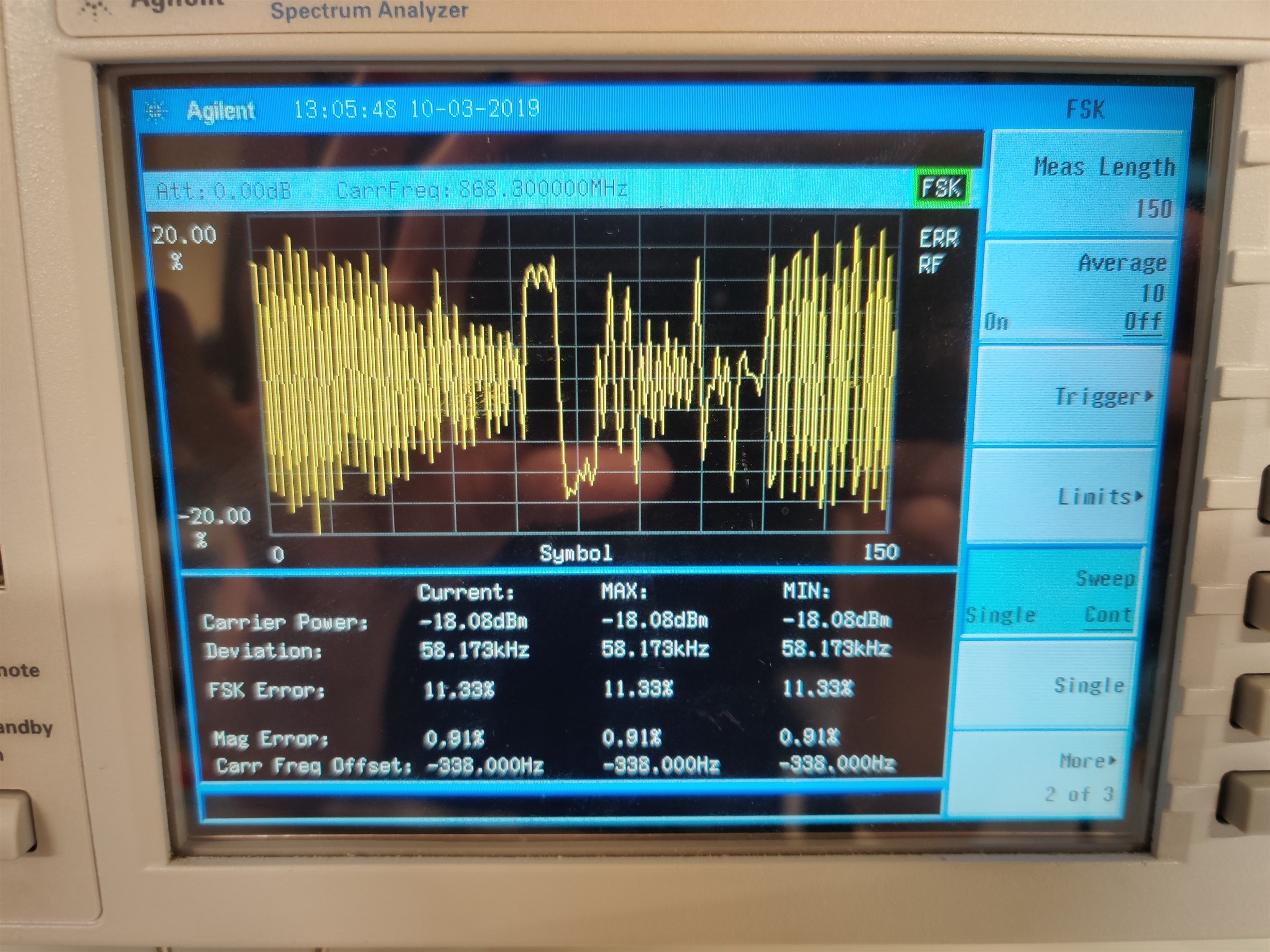
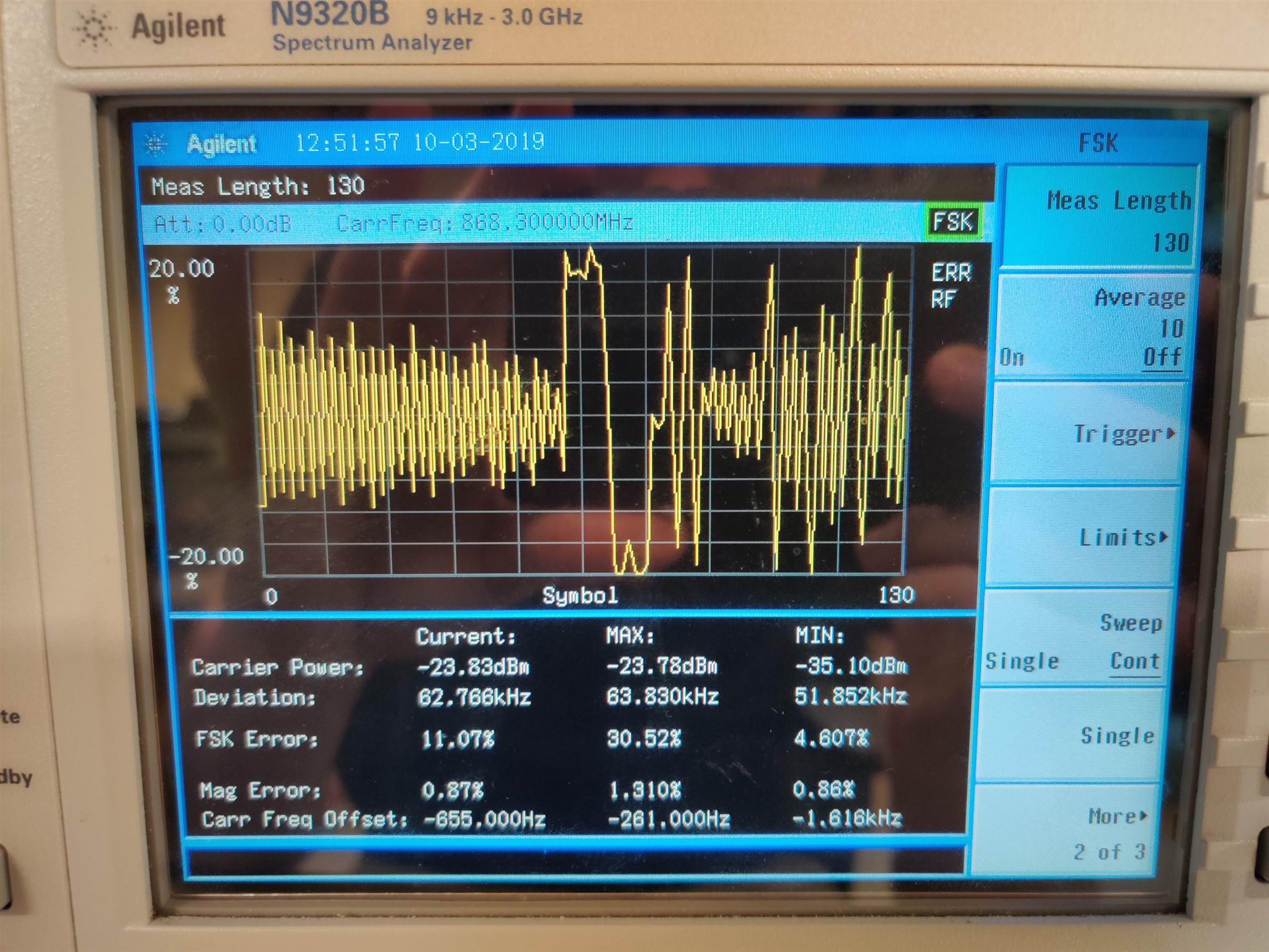
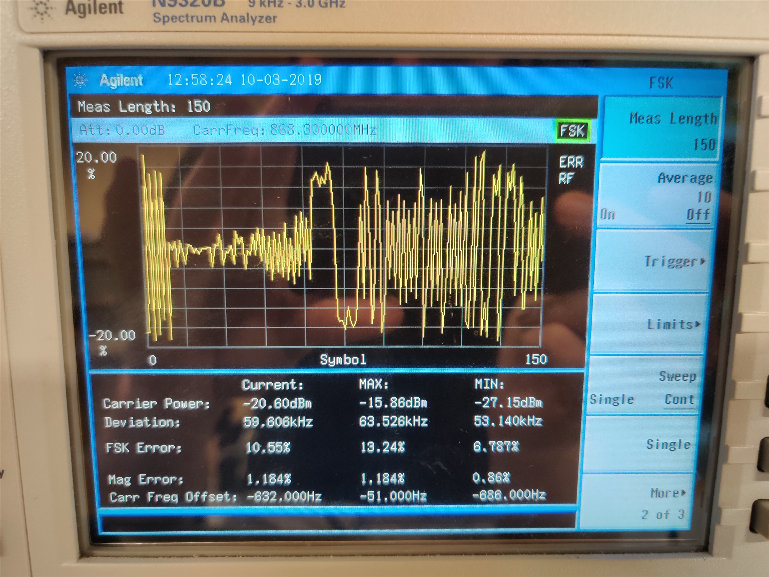
We observe that when the setup is running for a few days, the deviation of the RF signal decreases for certain parts of the transmitted signal. Attachments of this mail illustrate the measurements made.

The setup has the following relevant parameters:

  • The CC1101 is used for 868MHz operation
  • In FSCAL2 field VCO_CORE_H_EN is set to high in addition
  • In MCSM0 field FS_AUTOCAL is set to 1
  • Expected deviation is 50KHz

For testing purposes, I have also enabled the SCAL strobe before going to TX to perform manual calibration, but this does not resolve the issue observed. The errata was taken into account.

We expected the issue to be caused by some calibration issue of the VCO, but are not observing improvement. Could you elaborate on this issue? 

Many thanks for the response. 

Linda

  • - What is the background for these measurements? What type of issue do they observe?

    - Are they in cont. TX for days without any re-calibration of the VCO?  

    - In this case, is the carrier frequency also shifting or is it just the deviation that shift? 

    - If the carrier frequency shift, is the temperature stable or could they get some issues with that the reference frequency shifting due to various factors. 

    - It's a bit difficult to see what they measure (on) from the photos since the y axis shows error %. Is this a preamble or packets demodulated that are measured against the set carrier frequency/ deviation/ datarate?

  • Any update? 

  • very many thanks for your response.


    Indeed, the problem described was caused by not setting the Y-axis correctly. New measurements indicate the deviation is what we expected, but has some overshoot. This does not seem to be root cause of the issue I am investigating. Thanks for the response.


    I have a new question regarding the CC1310. After doing some tests, the symbol rate seems to tolerate a very small difference until the sync word is not heard or bytes are received incorrectly. This does not compare to the CC1101, which is able to receive the bytes correctly for the same packet.


    To be clear, we are using transparent mode for the CC1101 connected to a UART to transfer packets with 2% tolerance on baudrate. Over UART Manchester encoding is done by sending 4 bits as a byte. The baudrate is 38.4Kbps (effective 19.2Kbps).


    How can we improve the symbol rate tolerance for the radio configuration? What is the default/defined symbol rate tolerance for the CC1310 with the default RF patches?


    I have attached the settings we are using generated by SmartRF Studio.


    Many thanks again for the response.

    smartrf_settings_used.c
    // Start smartrf_settings
    
    // TX Power table size definition
    #define TX_POWER_TABLE_SIZE 18
    
    // TI-RTOS RF Mode Object
    static RF_Mode RF_prop = {
    	.rfMode = RF_MODE_PROPRIETARY_SUB_1,
    	.cpePatchFxn = &rf_patch_cpe_genfsk,
    	.mcePatchFxn = 0,
    	.rfePatchFxn = &rf_patch_rfe_genfsk,
    };
    
    // TX Power table
    // The RF_TxPowerTable_DEFAULT_PA_ENTRY macro is defined in RF.h and requires the following arguments:
    // RF_TxPowerTable_DEFAULT_PA_ENTRY(bias, gain, boost coefficient)
    // See the Technical Reference Manual for further details about the "txPower" Command field.
    // The PA settings require the CCFG_FORCE_VDDR_HH = 0 unless stated otherwise.
    static RF_TxPowerTable_Entry txPowerTable[TX_POWER_TABLE_SIZE] = {
    	{-10, RF_TxPowerTable_DEFAULT_PA_ENTRY(0, 3, 0, 4) },
    	{0, RF_TxPowerTable_DEFAULT_PA_ENTRY(1, 1, 0, 0) },
    	{1, RF_TxPowerTable_DEFAULT_PA_ENTRY(3, 3, 0, 8) },
    	{2, RF_TxPowerTable_DEFAULT_PA_ENTRY(2, 1, 0, 8) },
    	{3, RF_TxPowerTable_DEFAULT_PA_ENTRY(4, 3, 0, 10) },
    	{4, RF_TxPowerTable_DEFAULT_PA_ENTRY(5, 3, 0, 12) },
    	{5, RF_TxPowerTable_DEFAULT_PA_ENTRY(6, 3, 0, 12) },
    	{6, RF_TxPowerTable_DEFAULT_PA_ENTRY(7, 3, 0, 14) },
    	{7, RF_TxPowerTable_DEFAULT_PA_ENTRY(9, 3, 0, 16) },
    	{8, RF_TxPowerTable_DEFAULT_PA_ENTRY(11, 3, 0, 18) },
    	{9, RF_TxPowerTable_DEFAULT_PA_ENTRY(13, 3, 0, 22) },
    	{10, RF_TxPowerTable_DEFAULT_PA_ENTRY(19, 3, 0, 28) },
    	{11, RF_TxPowerTable_DEFAULT_PA_ENTRY(26, 3, 0, 40) },
    	{12, RF_TxPowerTable_DEFAULT_PA_ENTRY(24, 0, 0, 92) },
    	{13, RF_TxPowerTable_DEFAULT_PA_ENTRY(63, 0, 0, 83) }, // The original PA value (12.5 dBm) have been rounded to an integer value.
    	{14, RF_TxPowerTable_DEFAULT_PA_ENTRY(63, 0, 1, 83) }, // This setting requires CCFG_FORCE_VDDR_HH = 1.
    	{14, RF_TxPowerTable_DEFAULT_PA_ENTRY(63, 0, 1, 83) }, // This setting requires CCFG_FORCE_VDDR_HH = 1.
    	RF_TxPowerTable_TERMINATION_ENTRY,
    };
    
    // Overrides for CMD_PROP_RADIO_DIV_SETUP
    static UINT32 pOverrides[] = {
    	// override_use_patch_prop_genfsk.xml
    	// PHY: Use MCE ROM bank 4, RFE RAM patch
    	MCE_RFE_OVERRIDE(0,4,0,1,0,0), //lint !e961 !e514 Library defined
    	// override_synth_prop_863_930_div5.xml
    	// Synth: Set recommended RTRIM to 7
    	HW_REG_OVERRIDE(0x4038,0x0037),
    	// Synth: Set Fref to 4 MHz
    	(uint32_t)0x000684A3,
    	// Synth: Configure fine calibration setting
    	HW_REG_OVERRIDE(0x4020,0x7F00),
    	// Synth: Configure fine calibration setting
    	HW_REG_OVERRIDE(0x4064,0x0040),
    	// Synth: Configure fine calibration setting
    	(uint32_t)0xB1070503,
    	// Synth: Configure fine calibration setting
    	(uint32_t)0x05330523,
    	// Synth: Set loop bandwidth after lock to 20 kHz
    	(uint32_t)0x0A480583,
    	// Synth: Set loop bandwidth after lock to 20 kHz
    	(uint32_t)0x7AB80603,
    	// Synth: Configure VCO LDO (in ADI1, set VCOLDOCFG=0x9F to use voltage input reference)
    	ADI_REG_OVERRIDE(1,4,0x9F), //lint !e961 Library defined
    	// Synth: Configure synth LDO (in ADI1, set SLDOCTL0.COMP_CAP=1)
    	ADI_HALFREG_OVERRIDE(1,7,0x4,0x4), //lint !e961 Library defined
    	// Synth: Use 24 MHz XOSC as synth clock, enable extra PLL filtering
    	(uint32_t)0x02010403,
    	// Synth: Configure extra PLL filtering
    	(uint32_t)0x00108463,
    	// Synth: Increase synth programming timeout (0x04B0 RAT ticks = 300 us)
    	(uint32_t)0x04B00243,
    	// override_phy_rx_aaf_bw_0xd.xml
    	// Rx: Set anti-aliasing filter bandwidth to 0xD (in ADI0, set IFAMPCTL3[7:4]=0xD)
    	ADI_HALFREG_OVERRIDE(0,61,0xF,0xD), //lint !e961 Library defined
    	// override_phy_gfsk_rx.xml
    	// Rx: Set LNA bias current trim offset to 3
    	(uint32_t)0x00038883,
    	// Rx: Freeze RSSI on sync found event
    	HW_REG_OVERRIDE(0x6084,0x35F1),
    	// override_phy_gfsk_pa_ramp_agc_reflevel_0x1a.xml
    	// Tx: Configure PA ramping setting (0x41). Rx: Set AGC reference level to 0x1A.
    	HW_REG_OVERRIDE(0x6088,0x411A),
    	// Tx: Configure PA ramping setting
    	HW_REG_OVERRIDE(0x608C,0x8213),
    	// override_phy_rx_rssi_offset_5db.xml
    	// Rx: Set RSSI offset to adjust reported RSSI by +5 dB
    	(uint32_t)0x00FB88A3,
    	// TX power override
    	// Tx: Set PA trim to max (in ADI0, set PACTL0=0xF8)
    	ADI_REG_OVERRIDE(0,12,0xF8), //lint !e961 Library defined
    	(uint32_t)0xFFFFFFFF,
    };
    
    // CMD_PROP_RADIO_DIV_SETUP
    // Proprietary Mode Radio Setup Command for All Frequency Bands
    static rfc_CMD_PROP_RADIO_DIV_SETUP_t RF_cmdPropRadioDivSetup = {
    	.commandNo = 0x3807,
    	.status = 0x0000,
    	.pNextOp = 0, // INSERT APPLICABLE POINTER: (uint8_t*)&xxx
    	.startTime = 0x00000000,
    	.startTrigger = {
    		.triggerType = 0x0,
    		.bEnaCmd = 0x0,
    		.triggerNo = 0x0,
    		.pastTrig = 0x0,
    	},
    	.condition = {
    		.rule = 0x1,
    		.nSkip = 0x0,
    	},
    	.modulation = {
    		.modType = 0x0,
    		.deviation = 0xC8,
    	},
    	.symbolRate = {
    		.preScale = 0xF,
    		.rateWord = 0x624E,
    	},
    	.rxBw = 0x26,
    	.preamConf = {
    		.nPreamBytes = 0x6,
    		.preamMode = 0x0,
    	},
    	.formatConf = {
    		.nSwBits = 0x20,
    		.bBitReversal = 0x0,
    		.bMsbFirst = 0x1,
    		.fecMode = 0x0,
    		.whitenMode = 0x0,
    	},
    	.config = {
    		.frontEndMode = 0x0,
    		.biasMode = 0x1,
    		.analogCfgMode = 0x0,
    		.bNoFsPowerUp = 0x0,
    	},
    	.txPower = 0x2CCD,
    	.pRegOverride = pOverrides,
    	.centerFreq = 0x0364,
    	.intFreq = (SINT16)0x8000,
    	.loDivider = 0x05,
    };
    
    // CMD_PROP_RX_ADV
    // Proprietary Mode Advanced Receive Command
    static rfc_CMD_PROP_RX_ADV_t RF_cmdPropRxAdv = {
    	.commandNo = 0x3804,
    	.status = 0x0000,
    	.pNextOp = 0, // INSERT APPLICABLE POINTER: (uint8_t*)&xxx
    	.startTime = 0x00000000,
    	.startTrigger = {
    		.triggerType = TRIG_NOW,
    		.bEnaCmd = 0x0,
    		.triggerNo = 0x0,
    		.pastTrig = 0x1,
    	},
    	.condition = {
    		.rule = COND_ALWAYS,
    		.nSkip = 0x0,
    	},
    	.pktConf = {
    		.bFsOff = 0x0,
    		.bRepeatOk = 0x1,
    		.bRepeatNok = 0x1,
    		.bUseCrc = 0x0,
    		.bCrcIncSw = 0x0,
    		.bCrcIncHdr = 0x0,
    		.endType = 0x0,
    		.filterOp = 0x0,
    	},
    	.rxConf = {
    		.bAutoFlushIgnored = 0x0,
    		.bAutoFlushCrcErr = 0x0,
    		.bIncludeHdr = 0x0,
    		.bIncludeCrc = 0x0,
    		.bAppendRssi = 0x0,
    		.bAppendTimestamp = 0x0,
    		.bAppendStatus = 0x0,
    	},
    	.syncWord0 = 0xC0166555,
    	.syncWord1 = 0x00000000,
    	.maxPktLen = 0x0,
    	.hdrConf = {
    		.numHdrBits = 0x0,
    		.lenPos = 0x0,
    		.numLenBits = 0x0,
    	},
    	.addrConf = {
    		.addrType = 0x0,
    		.addrSize = 0x0,
    		.addrPos = 0x0,
    		.numAddr = 0x0,
    	},
    	.lenOffset = 0x00,
    	.endTrigger = {
    		.triggerType = 0x0,
    		.bEnaCmd = 0x0,
    		.triggerNo = 0x0,
    		.pastTrig = 0x0,
    	},
    	.endTime = 0x00000000,
    	.pAddr = 0, // INSERT APPLICABLE POINTER: (uint8_t*)&xxx
    	.pQueue = 0, // INSERT APPLICABLE POINTER: (dataQueue_t*)&xxx
    	.pOutput = 0, // INSERT APPLICABLE POINTER: (uint8_t*)&xxx
    };
    
    // CMD_PROP_TX_ADV
    // Proprietary Mode Advanced Transmit Command
    static rfc_CMD_PROP_TX_ADV_t RF_cmdPropTxAdv = {
    	.commandNo = 0x3803,
    	.status = 0x0000,
    	.pNextOp = 0, // INSERT APPLICABLE POINTER: (uint8_t*)&xxx
    	.startTime = 0x00000000,
    	.startTrigger = {
    		.triggerType = TRIG_NOW,
    		.bEnaCmd = 0x0,
    		.triggerNo = 0x0,
    		.pastTrig = 0x1,
    	},
    	.condition = {
    		.rule = COND_ALWAYS,
    		.nSkip = 0x0,
    	},
    	.pktConf = {
    		.bFsOff = 0x0,
    		.bUseCrc = 0x0,
    		.bCrcIncSw = 0x0,
    		.bCrcIncHdr = 0x0,
    	},
    	.numHdrBits = 0x0,
    	.pktLen = 0x0,
    	.startConf = {
    		.bExtTxTrig = 0x0,
    		.inputMode = 0x0,
    		.source = 0x0,
    	},
    	.preTrigger = {
    		.triggerType = 0x0,
    		.bEnaCmd = 0x0,
    		.triggerNo = 0x0,
    		.pastTrig = 0x0,
    	},
    	.preTime = 0x00000000,
    	.syncWord = 0x5FF00599,
    	.pPkt = 0, // INSERT APPLICABLE POINTER: (uint8_t*)&xxx
    };
    
    // CMD_TX_TEST
    // Transmitter Test Command
    static rfc_CMD_TX_TEST_t RF_cmdTxTest =
    {
    	.commandNo = 0x0808,
    	.status = 0x0000,
    	.pNextOp = 0, // INSERT APPLICABLE POINTER: (uint8_t*)&xxx
    	.startTime = 0x00000000,
    	.startTrigger = {
    		.triggerType = TRIG_NOW,
    		.bEnaCmd = 0x0,
    		.triggerNo = 0x0,
    		.pastTrig = 0x0,
    	},
    	.condition = {
    		.rule = COND_ALWAYS,
    		.nSkip = 0x0,
    	},
    	.config = {
    		.bUseCw = 0x0,
    		.bFsOff = 0x0,
    		.whitenMode = 0x0,
    	},
    	.__dummy0 = 0x00,
    	.txWord = 0,
    	.__dummy1 = 0x00,
    	.endTrigger = {
    		.triggerType = 0x1,
    		.bEnaCmd = 0x0,
    		.triggerNo = 0x0,
    		.pastTrig = 0x0,
    	},
    	.syncWord = 0x0,
    	.endTime = 0x00000000,
    };
    
    // End smartrf_settings

  • Before I start to dig too much into what is possible on the CC1310 side: You write that you use transparent mode on the CC1101 side. The CC1310 require preamble + sync + payload. Do you have this structure in the stream you send from the CC1101 side? 

  • Hi Ter,

    Yes, the CC1101 side adheres this structure. It sends a preamble, sync word and payload

  • To get 2 % symbolrate tolerance you need a patch. You can try to see if you can use  and try to use your required datarate, deviation and sync word in the API settings described in 2.1.1

  • Ter, the issue is not resolved. I'm re adding a summary of  the issue here:

    We are using the CC1310 to communicate with a CC1101 (and vice versa). What we’ve observed is that the CC1310 has a low bit rate offset tolerance.


    The CC1101 side is set-up in transparent mode and connected to a UART. Through the UART, packets are sent with a 2% tolerance on the baudrate. Due to our use case, we cannot use Manchester encoding provided by the driver of the CC1310. The CC1310 is set-up according to the settings generated through SmartRF in the file ‘smartrf_settings_used.c’ which I can I can provide directly.

    We’ve attempted to apply the wmbus s-mode patch, as this offers a higher bit rate tolerance. But this patch does Manchester coding, which is not applicable for our use case.


    When the baudrate of the UART at the CC1101 side is accurate, communication works. But when the baudrate is off but within 2% tolerance, communication fails. The sync word is often heard, and bytes are received incorrectly.


    We are looking for a solution to increase the bit rate tolerance of the CC1310

    Can you help?

  • see further commentary below

  • Hi

    The CC1310 is not capable of handling 2% data rate tolerance.

    The s-mode patch can handle this, but unfortunately is uses Manchester encoding/decoding, which is not possible to disable.

    The only thing the customer can try to do is to use the CC1310 in transparent mode, getting the data out on a pin, and then do all sampling and processing themselves.

    BR

    Siri

  • thanks, but what is the maximum data rate tolerance the CC1310 can handle with their configuration?

  • The data rate offset tolerance for the 50 kbps sesttings in SmartRF Studio is 0.16 %

    BR

    Siri

  • Hello,

    Can you help with a response on my last entry? What is the maximum data rate tolerance the CC1310 can handle with their configuration??

  • Siri,

    Many thanks for the feedback, although this does not quite help the use case here.

    >>>>>>

    We hoped that our specific use case would give a much higher tolerance. But this looks like the tolerance is always 0.16%. Is that correct?

    Do we have a SW UART available for them so they could try transparent mode?

    Is there another option they can consider?


  • Not sure why you think that your use case should be able to increase the data rate tolerance compared to the data sheet numbers?

    Unfortunately we do not have any example code for trannsparent mode.

    The customer needs to look at


    to see how RX Data (MCE_GPO1)can be routed to a pin.

    I see that TER has suggested to try the S-mode patch. You say that it cannot be used because the patch uses Manchester and that the customer is not doing this.

    However, in an earlier post you write:

    "To be clear, we are using transparent mode for the CC1101 connected to a UART to transfer packets with 2% tolerance on baudrate. Over UART Manchester encoding is done by sending 4 bits as a byte. The baudrate is 38.4Kbps (effective 19.2Kbps)"

    Are the TX data Manchester encoded or not, and have the actually tried to use the patch?

    BR

    Siri

  • Closed due to lack of feedback.

    Siri