This thread has been locked.

If you have a related question, please click the "Ask a related question" button in the top right corner. The newly created question will be automatically linked to this question.

LAUNCHXL-CC13-90: Migrate from CC1310 to CC13-90

Part Number: LAUNCHXL-CC13-90
Other Parts Discussed in Thread: CC1310, , LAUNCHXL-CC1310, CC1190, WMBUS

Hi,

We developed a project on the LAUNCHXL-CC1310 development kit and then designed our custom board based on the CC1310. Now we want to use the same project on the LAUNCHXL-CC13-90 development kit. After that, we will also design our custom board and program it.

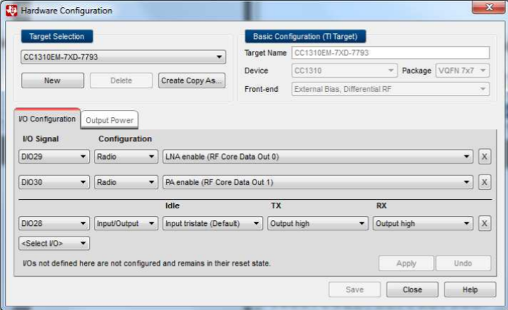
I was wondering if we need to change anything in our software to adapt to this change? In the Smart RF Studio, when I connect to the LAUNCHXL-CC13-90 and try to use the config file saved for LAUNCHXL-CC1310, I get an error regarding mismatched parameters. I guess it is related to transmit power because the options in the transmit power are different in these kits. 

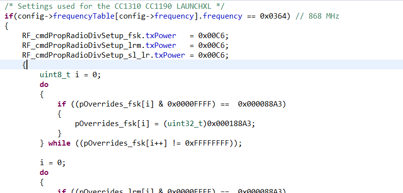
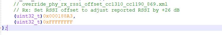
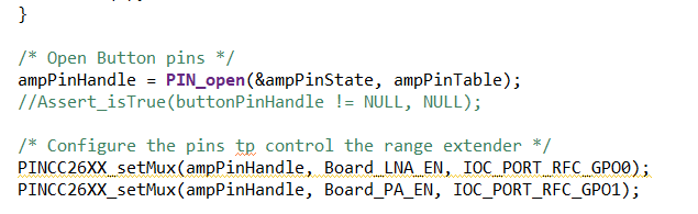
So I wondered what kind of changes should I do on my project to migrate it to LAUNCHXL-CC13-90 design. Is there anything needs to be done in order to activate the amplifier for example?

Thanks,

Abdullah.

  • See the "Controlling the CC1190"  http://www.ti.com/lit/an/swra542/swra542.pdf on how to control the CC1190. Also the app note outline the required software changes. Typically this is the change in RSSI offset and the txpower table. The easiest is to use SmartRF Studio, select the CC13-90 LP under "Target configuration" and export the settings. 

  • Hi TER,

    Thanks for the answer. The document says that "HGM should be tied high or low using the pin driver" and it also gives an example code for this. When we import settings from the SmartRF Studio, do we still need to control these pins on our software? I didn't see anything related to these pins in the exported smartrf_settings.c file.

  • Yes.

    SmartRF Studio exports the code that is required to setup the radio part correctly but you need to add the control of the CC1190 in your code. 

  • Then I didn't understand what does the Hardware Configuration window do.

    Q1: The smartrf_settings.c file does not have anything related to these. So why are we doing this setting?

    Q2: If we need to do the io control in the software, how can the SmartRF Studio achieve 26dBm tx power with only rf settings?

    Thanks.

  • Addition: I run the SmartRF Studio packet RX for both development kits. The RSSI values for the received packets on the CC13-90 kit are worse than the CC1310 kit. Am I missing something? Both kits are used as it is: the pcb antenna. Only difference on the settings are the TX power is 26dBm for the CC13-90 kit and 14dBm for the CC1310 kit. But I'm not transmitting anything, I'm just receiving packets and checking the RSSI. Is this also rely on the tx power? Or is there any other setting to increase the receive sensitivity?

  • Hi,

    I checked the example of rfPacketErrorRate. In this example, I searched for the changes for CC1310-90 LAUNCHXL kit. There are 2 changes for this kit:

    First one is to assign the RFIO to PA and LNA pins as below (HSM is not assigned???):

    The second change is the RSSI offset register override. I think I don't need this in my project because when I imported the settings from SmartRF Studio, it was already done on my override list. 

    This is the override done in the example:

    And this is my override taken from the SmartRF Studio:

    My question is: when we assign the RFIO to PA and LNA, does the RF core drive them automatically for the best possible range? As I read from the document you provided, RX HGM and TX HGM modes require different levels for these signals. In my project, I both need RX and TX. When I send an RX command or TX command, does the RF core changes the state of these pins as below?:

  • "Hardware Configuration window": This is if you want to test a custom board with SmartRF Studio. This enables you to set the correct pins for, in this case, control of CC1190. 

     Did you ad the section in the TRM that the app note referred to ("Control External LNA/PA (Range Extender) With I/Os section" in http://www.ti.com/lit/ug/swcu117h/swcu117h.pdf? If you look at table 11.1 you will see that the signals used are set automatically by the RF code to have the correct state in RX, TX and standbd and CC1190 will be in the wanted state. 

  • Hi TER,

    Thanks for the answer. But I still don't understand something. If we import the settings from the SmartRF Studio to our project, don't we still need to add the code to assign the RF_GPO pins to PA and LNA pins? If we need them, how can we test the amplifier over the SmartRF Studio? Because it only uses the RF settings...

    Edit: I also couldn't get the answer to whether the RF core changes the states of the PA and LNA when we switch between RX to TX. We need to achieve maximum range in RX and TX for our range extender.

  • Setting the signals required to control CC1190 are done differently.

    - SmartRF Studio  uses the Hardware Configuration window. The LNA enable and PA enable signals are the same as used in the code example so the functionality is the same. The settings in this window is not exported as code, it's just for testing in SmartRF Studio.

    - Code: If you want to test the board using code with CCS/ IAR, you need to add lines as in the example code to your code to set the wanted control signals. 

  • Hi TER,

    I added the pin assignments to my project like below:

    Q1: There is no CC1310 alternative function for PINCC26XX_setmux function. Can I use this function in my CC1310?

    Q2: Now when I switch between the RX and TX modes, the RF core will drive the PA and LNA pins according to the below table. Am I right?

  • Hi,

    I did an RX test on two LP boards: LAUNCHXL-CC1310 and LAUNCHXL-CC13-90

    I compared the RSSI values of the packets from a water meter. I just changed the smartrf_settings.c files and added PA, LNA and HGM io control to enable the CC1190.

    The results are almost worse in the LAUNCHXL-CC13-90 compared to the LAUNCHXL-CC1310 board. I attached my rf source file. There is the AMP_ENABLED condition that adds the io control for the amplifier. I also attached my smartrf_setting.c files for each LP boards project. The rest is common for both projects.

    Can you please tell me if I'm missing something? 

    amp.c
    /***** Includes *****/
    /* Standard C Libraries */
    #include <stdlib.h>
    
    /* TI Drivers */
    #include <ti/drivers/rf/RF.h>
    #include <ti/sysbios/BIOS.h>
    #include DeviceFamily_constructPath(driverlib/rf_prop_mailbox.h)
    
    /* Application Header files */
    #include "rf_layer.h"
    #include "rf/RFQueue.h"
    #include "smartrf_settings/smartrf_settings.h"
    #include <ti/devices/cc13x0/driverlib/sys_ctrl.h>
    #include "board/CC1310_LAUNCHXL.h"
    
    /***** Prototypes *****/
    static void callback(RF_Handle h, RF_CmdHandle ch, RF_EventMask e);
    
    /***** Variable declarations *****/
    static RF_Object rfObject;
    static RF_Handle rfHandle;
    
    /* Buffer which contains all Data Entries for receiving data.
     * Pragmas are needed to make sure this buffer is 4 byte aligned (requirement from the RF Core) */
    #if defined(__TI_COMPILER_VERSION__)
    #pragma DATA_ALIGN (rxDataEntryBuffer, 4);
    static uint8_t
    rxDataEntryBuffer[RF_QUEUE_DATA_ENTRY_BUFFER_SIZE(NUM_DATA_ENTRIES,
                                                      ENCODED_DATA_LEN,
                                                      NUM_APPENDED_BYTES)];
    #elif defined(__IAR_SYSTEMS_ICC__)
    #pragma data_alignment = 4
    static uint8_t
    rxDataEntryBuffer[RF_QUEUE_DATA_ENTRY_BUFFER_SIZE(NUM_DATA_ENTRIES,
                                                      ENCODED_DATA_LEN,
                                                      NUM_APPENDED_BYTES)];
    #elif defined(__GNUC__)
    static uint8_t
    rxDataEntryBuffer[RF_QUEUE_DATA_ENTRY_BUFFER_SIZE(NUM_DATA_ENTRIES,
                                                      ENCODED_DATA_LEN,
                                                      NUM_APPENDED_BYTES)]
                                                      __attribute__((aligned(4)));
    #else
    #error This compiler is not supported.
    #endif
    
    /* Receive dataQueue for RF Core to fill in data */
    static dataQueue_t dataQueue;
    static rfc_dataEntryGeneral_t* currentDataEntry;
    
    /* This buffer is not directly accessed by the application */
    static RFMailboxMsgObj rf_mailboxBuffer[NUMMSGS];
    Mailbox_Handle rf_mbxHandle;
    
    Mailbox_Params mbxParams;
    Mailbox_Struct mbxStruct;
    
    #if AMP_ENABLED
    
    PIN_Handle ampPinHandle;
    PIN_State ampPinState;
    
    #define Board_HGM             CC1310_LAUNCHXL_DIO28_ANALOG
    #define Board_LNA_EN          CC1310_LAUNCHXL_DIO29_ANALOG
    #define Board_PA_EN           CC1310_LAUNCHXL_DIO30_ANALOG
    
    /*
    Application button pin configuration table.
    Buttons interrupts are configured to trigger on falling edge.
    */
    PIN_Config ampPinTable[] =
    {
        Board_HGM | PIN_GPIO_OUTPUT_EN | PIN_GPIO_HIGH | PIN_PUSHPULL | PIN_DRVSTR_MAX,
        Board_LNA_EN | PIN_GPIO_OUTPUT_EN | PIN_GPIO_LOW | PIN_PUSHPULL | PIN_DRVSTR_MAX,
        Board_PA_EN | PIN_GPIO_OUTPUT_EN | PIN_GPIO_LOW | PIN_PUSHPULL | PIN_DRVSTR_MAX,
    
        PIN_TERMINATE,
    };
    
    #endif
    
    void *packRxThread(void *arg0)
    {
    
        /* Construct a Mailbox instance */
        Mailbox_Params_init(&mbxParams);
        mbxParams.buf = (Ptr)rf_mailboxBuffer;
        mbxParams.bufSize = sizeof(rf_mailboxBuffer);
        Mailbox_construct(&mbxStruct, sizeof(RFMsgObj), NUMMSGS, &mbxParams, NULL);
        rf_mbxHandle = Mailbox_handle(&mbxStruct);
    
        RF_Params rfParams;
        RF_Params_init(&rfParams);
    
        if( RFQueue_defineQueue(&dataQueue,
                                rxDataEntryBuffer,
                                sizeof(rxDataEntryBuffer),
                                NUM_DATA_ENTRIES,
                                ENCODED_DATA_LEN + NUM_APPENDED_BYTES))
        {
            /* Failed to allocate space for all data entries */
            while(1);
        }
    
    #if AMP_ENABLED
        /* Open Button pins */
        ampPinHandle = PIN_open(&ampPinState, ampPinTable);
        //Assert_isTrue(buttonPinHandle != NULL, NULL);
    
        /* Configure the pins to control the range extender */
        IOCPortConfigureSet(Board_LNA_EN, IOC_PORT_RFC_GPO0, IOC_IOMODE_NORMAL);
        IOCPortConfigureSet(Board_PA_EN, IOC_PORT_RFC_GPO1, IOC_IOMODE_NORMAL);
    
        /* RX High Gain Mode */
        PIN_setOutputValue(ampPinHandle, Board_HGM, 1);
        PIN_setOutputValue(ampPinHandle, Board_LNA_EN, 1);
        PIN_setOutputValue(ampPinHandle, Board_PA_EN, 0);
    
        /* TX High Gain Mode */
        //PIN_setOutputValue(ampPinHandle, Board_HGM, 1);
        //PIN_setOutputValue(ampPinHandle, Board_LNA_EN, 0);
        //PIN_setOutputValue(ampPinHandle, Board_PA_EN, 1);
    #endif
    
        /* Modify CMD_PROP_RX command for application needs */
        /* Set the Data Entity queue for received data */
        RF_cmdPropRx.pQueue = &dataQueue;
        /* Implement packet length filtering to avoid PROP_ERROR_RXBUF */
        RF_cmdPropRx.maxPktLen = ENCODED_DATA_LEN;
        RF_cmdPropRx.pktConf.bRepeatOk = 0x1;
        RF_cmdPropRx.pktConf.bRepeatNok = 0x1;
        RF_cmdPropRx.pktConf.bUseCrc = 0x0;
        RF_cmdPropRx.rxConf.bIncludeHdr = 0x0;
        RF_cmdPropRx.rxConf.bAppendRssi = 0x1;
        RF_cmdPropRx.rxConf.bAppendStatus = 0x0;
    
        /* Request access to the radio */
    #if defined(DeviceFamily_CC26X0R2)
        rfHandle = RF_open(&rfObject, &RF_prop, (RF_RadioSetup*)&RF_cmdPropRadioSetup, &rfParams);
    #else
        rfHandle = RF_open(&rfObject, &RF_prop, (RF_RadioSetup*)&RF_cmdPropRadioDivSetup, &rfParams);
    #endif// DeviceFamily_CC26X0R2
    
        /* Set the frequency */
        RF_postCmd(rfHandle, (RF_Op*)&RF_cmdFs, RF_PriorityNormal, NULL, 0);
    
        /* Enter RX mode and stay forever in RX */
        RF_EventMask terminationReason = RF_runCmd(rfHandle, (RF_Op*)&RF_cmdPropRx,
                                                   RF_PriorityHigh, &callback,
                                                   RF_EventRxEntryDone);
    
        switch(terminationReason)
        {
            case RF_EventLastCmdDone:
                // A stand-alone radio operation command or the last radio
                // operation command in a chain finished.
                //printf("RF_EventLastCmdDone\r\n");
                break;
            case RF_EventCmdCancelled:
                // Command cancelled before it was started; it can be caused
                // by RF_cancelCmd() or RF_flushCmd().
                //printf("RF_EventCmdCancelled\r\n");
                break;
            case RF_EventCmdAborted:
                // Abrupt command termination caused by RF_cancelCmd() or
                // RF_flushCmd().
                //printf("RF_EventCmdAborted\r\n");
                break;
            case RF_EventCmdStopped:
                // Graceful command termination caused by RF_cancelCmd() or
                // RF_flushCmd().
                //printf("RF_EventCmdStopped\r\n");
                break;
            default:
                // Uncaught error event
                //printf("default1\r\n");
                SysCtrlSystemReset();
                while(1);
        }
    
        uint32_t cmdStatus = ((volatile RF_Op*)&RF_cmdPropRx)->status;
        switch(cmdStatus)
        {
            case PROP_DONE_OK:
                // Packet received with CRC OK
                //printf("PROP_DONE_OK\r\n");
                break;
            case PROP_DONE_RXERR:
                // Packet received with CRC error
                //printf("PROP_DONE_RXERR\r\n");
                break;
            case PROP_DONE_RXTIMEOUT:
                // Observed end trigger while in sync search
                //printf("PROP_DONE_RXTIMEOUT\r\n");
                break;
            case PROP_DONE_BREAK:
                // Observed end trigger while receiving packet when the command is
                // configured with endType set to 1
                //printf("PROP_DONE_BREAK\r\n");
                break;
            case PROP_DONE_ENDED:
                // Received packet after having observed the end trigger; if the
                // command is configured with endType set to 0, the end trigger
                // will not terminate an ongoing reception
                //printf("PROP_DONE_ENDED\r\n");
                break;
            case PROP_DONE_STOPPED:
                // received CMD_STOP after command started and, if sync found,
                // packet is received
                //printf("PROP_DONE_STOPPED\r\n");
                break;
            case PROP_DONE_ABORT:
                // Received CMD_ABORT after command started
                //printf("PROP_DONE_ABORT\r\n");
                break;
            case PROP_ERROR_RXBUF:
                // No RX buffer large enough for the received data available at
                // the start of a packet
                //printf("PROP_ERROR_RXBUF\r\n");
                break;
            case PROP_ERROR_RXFULL:
                // Out of RX buffer space during reception in a partial read
                //printf("PROP_ERROR_RXFULL\r\n");
                break;
            case PROP_ERROR_PAR:
                // Observed illegal parameter
                //printf("PROP_ERROR_PAR\r\n");
                break;
            case PROP_ERROR_NO_SETUP:
                // Command sent without setting up the radio in a supported
                // mode using CMD_PROP_RADIO_SETUP or CMD_RADIO_SETUP
                //printf("PROP_ERROR_NO_SETUP\r\n");
                break;
            case PROP_ERROR_NO_FS:
                // Command sent without the synthesizer being programmed
                //printf("PROP_ERROR_NO_FS\r\n");
                break;
            case PROP_ERROR_RXOVF:
                // RX overflow observed during operation
                //printf("PROP_ERROR_RXOVF\r\n");
                break;
            default:
                // Uncaught error event - these could come from the
                // pool of states defined in rf_mailbox.h
                //printf("default2\r\n");
                SysCtrlSystemReset();
                while(1);
        }
    
        SysCtrlSystemReset();
        while(1);
    }
    
    
    RFMsgObj RFmsg;
    void callback(RF_Handle h, RF_CmdHandle ch, RF_EventMask e)
    {
        if (e & RF_EventRxEntryDone)
        {
            /* Get current unhandled data entry */
            currentDataEntry = RFQueue_getDataEntry();
    
            memcpy(RFmsg.buf, (uint8_t*)(&currentDataEntry->data), currentDataEntry->length);
    
            if (Mailbox_post(rf_mbxHandle, &RFmsg, BIOS_NO_WAIT)) {
    
                ////printf("1Mailbox Write \r\n");
            }
            else {
    
                ////printf("1Mailbox Write Failed\r\n");
            }
    
            RFQueue_nextEntry();
        }
    }
    

    smartrf_settings_cc1190.c
    //*********************************************************************************
    // Generated by SmartRF Studio version 2.16.0 (build#215)
    // The applied template is compatible with CC13x0 SDK version 2.10.xx.xx or newer.
    // Device: CC1310 Rev. B (2.1).
    //
    //*********************************************************************************
    
    
    //*********************************************************************************
    // Parameter summary
    // RX Address0: 0xAA
    // RX Address1: 0xBB
    // RX Address Mode: No address check
    // Frequency: 868.95001 MHz
    // Data Format: Serial mode disable 
    // Deviation: 50.000 kHz
    // Fixed Packet Length: 20
    // Packet Length Config: Fixed
    // Max Packet Length: 255
    // Packet Data: 255 
    // RX Filter BW: 155 kHz
    // Symbol Rate: 100.00000 kBaud
    // Sync Word Length: 16 Bits
    // TX Power: 26 dBm
    // Whitening: No whitening 
    
    #include <ti/devices/DeviceFamily.h>
    #include DeviceFamily_constructPath(driverlib/rf_mailbox.h)
    #include DeviceFamily_constructPath(driverlib/rf_common_cmd.h)
    #include DeviceFamily_constructPath(driverlib/rf_prop_cmd.h)
    #include <ti/drivers/rf/RF.h>
    #include DeviceFamily_constructPath(rf_patches/rf_patch_cpe_genfsk.h)
    #include DeviceFamily_constructPath(rf_patches/rf_patch_rfe_genfsk.h)
    #include "smartrf_settings.h"
    
    
    // TI-RTOS RF Mode Object
    RF_Mode RF_prop =
    {
        .rfMode = RF_MODE_PROPRIETARY_SUB_1,
        .cpePatchFxn = &rf_patch_cpe_genfsk,
        .mcePatchFxn = 0,
        .rfePatchFxn = &rf_patch_rfe_genfsk
    };
    
    
    // Overrides for CMD_PROP_RADIO_DIV_SETUP
    uint32_t pOverrides[] =
    {
        // override_use_patch_prop_genfsk.xml
        // PHY: Use MCE ROM bank 4, RFE RAM patch
        MCE_RFE_OVERRIDE(0,4,0,1,0,0),
        // override_synth_prop_863_930_div5.xml
        // Synth: Set recommended RTRIM to 7
        HW_REG_OVERRIDE(0x4038,0x0037),
        // Synth: Set Fref to 4 MHz
        (uint32_t)0x000684A3,
        // Synth: Configure fine calibration setting
        HW_REG_OVERRIDE(0x4020,0x7F00),
        // Synth: Configure fine calibration setting
        HW_REG_OVERRIDE(0x4064,0x0040),
        // Synth: Configure fine calibration setting
        (uint32_t)0xB1070503,
        // Synth: Configure fine calibration setting
        (uint32_t)0x05330523,
        // Synth: Set loop bandwidth after lock to 20 kHz
        (uint32_t)0x0A480583,
        // Synth: Set loop bandwidth after lock to 20 kHz
        (uint32_t)0x7AB80603,
        // Synth: Configure VCO LDO (in ADI1, set VCOLDOCFG=0x9F to use voltage input reference)
        ADI_REG_OVERRIDE(1,4,0x9F),
        // Synth: Configure synth LDO (in ADI1, set SLDOCTL0.COMP_CAP=1)
        ADI_HALFREG_OVERRIDE(1,7,0x4,0x4),
        // Synth: Use 24 MHz XOSC as synth clock, enable extra PLL filtering
        (uint32_t)0x02010403,
        // Synth: Configure extra PLL filtering
        (uint32_t)0x00108463,
        // Synth: Increase synth programming timeout (0x04B0 RAT ticks = 300 us)
        (uint32_t)0x04B00243,
        // override_phy_rx_aaf_bw_0xd.xml
        // Rx: Set anti-aliasing filter bandwidth to 0xD (in ADI0, set IFAMPCTL3[7:4]=0xD)
        ADI_HALFREG_OVERRIDE(0,61,0xF,0xD),
        // override_phy_gfsk_rx.xml
        // Rx: Set LNA bias current trim offset to 3
        (uint32_t)0x00038883,
        // Rx: Freeze RSSI on sync found event
        HW_REG_OVERRIDE(0x6084,0x35F1),
        // override_phy_gfsk_pa_ramp_agc_reflevel_0x1a.xml
        // Tx: Configure PA ramping setting (0x41). Rx: Set AGC reference level to 0x1A.
        HW_REG_OVERRIDE(0x6088,0x411A),
        // Tx: Configure PA ramping setting
        HW_REG_OVERRIDE(0x608C,0x8213),
        // override_phy_rx_rssi_offset_cc1310_cc1190_869.xml
        // Rx: Set RSSI offset to adjust reported RSSI by +26 dB
        (uint32_t)0x000188A3,
        (uint32_t)0xFFFFFFFF
    };
    
    
    // CMD_PROP_RADIO_DIV_SETUP
    // Proprietary Mode Radio Setup Command for All Frequency Bands
    rfc_CMD_PROP_RADIO_DIV_SETUP_t RF_cmdPropRadioDivSetup =
    {
        .commandNo = 0x3807,
        .status = 0x0000,
        .pNextOp = 0, // INSERT APPLICABLE POINTER: (uint8_t*)&xxx
        .startTime = 0x00000000,
        .startTrigger.triggerType = 0x0,
        .startTrigger.bEnaCmd = 0x0,
        .startTrigger.triggerNo = 0x0,
        .startTrigger.pastTrig = 0x0,
        .condition.rule = 0x1,
        .condition.nSkip = 0x0,
        .modulation.modType = 0x1,
        .modulation.deviation = 0xC8,
        .symbolRate.preScale = 0xF,
        .symbolRate.rateWord = 0x10000,
        .symbolRate.decimMode = 0x0,
        .rxBw = 0x26,
        .preamConf.nPreamBytes = 0x4,
        .preamConf.preamMode = 0x0,
        .formatConf.nSwBits = 0x10,
        .formatConf.bBitReversal = 0x0,
        .formatConf.bMsbFirst = 0x1,
        .formatConf.fecMode = 0x0,
        .formatConf.whitenMode = 0x0,
        .config.frontEndMode = 0x0,
        .config.biasMode = 0x1,
        .config.analogCfgMode = 0x0,
        .config.bNoFsPowerUp = 0x0,
        .txPower = 0x00CB,
        .pRegOverride = pOverrides,
        .centerFreq = 0x0364,
        .intFreq = 0x8000,
        .loDivider = 0x05
    };
    
    
    // CMD_FS
    // Frequency Synthesizer Programming Command
    rfc_CMD_FS_t RF_cmdFs =
    {
        .commandNo = 0x0803,
        .status = 0x0000,
        .pNextOp = 0, // INSERT APPLICABLE POINTER: (uint8_t*)&xxx
        .startTime = 0x00000000,
        .startTrigger.triggerType = 0x0,
        .startTrigger.bEnaCmd = 0x0,
        .startTrigger.triggerNo = 0x0,
        .startTrigger.pastTrig = 0x0,
        .condition.rule = 0x1,
        .condition.nSkip = 0x0,
        .frequency = 0x0364,
        .fractFreq = 0xF334,
        .synthConf.bTxMode = 0x0,
        .synthConf.refFreq = 0x0,
        .__dummy0 = 0x00,
        .__dummy1 = 0x00,
        .__dummy2 = 0x00,
        .__dummy3 = 0x0000
    };
    
    
    // CMD_PROP_RX
    // Proprietary Mode Receive Command
    rfc_CMD_PROP_RX_t RF_cmdPropRx =
    {
        .commandNo = 0x3802,
        .status = 0x0000,
        .pNextOp = 0, // INSERT APPLICABLE POINTER: (uint8_t*)&xxx
        .startTime = 0x00000000,
        .startTrigger.triggerType = 0x0,
        .startTrigger.bEnaCmd = 0x0,
        .startTrigger.triggerNo = 0x0,
        .startTrigger.pastTrig = 0x0,
        .condition.rule = 0x1,
        .condition.nSkip = 0x0,
        .pktConf.bFsOff = 0x0,
        .pktConf.bRepeatOk = 0x0,
        .pktConf.bRepeatNok = 0x0,
        .pktConf.bUseCrc = 0x1,
        .pktConf.bVarLen = 0x0,
        .pktConf.bChkAddress = 0x0,
        .pktConf.endType = 0x0,
        .pktConf.filterOp = 0x0,
        .rxConf.bAutoFlushIgnored = 0x0,
        .rxConf.bAutoFlushCrcErr = 0x0,
        .rxConf.bIncludeHdr = 0x1,
        .rxConf.bIncludeCrc = 0x0,
        .rxConf.bAppendRssi = 0x0,
        .rxConf.bAppendTimestamp = 0x0,
        .rxConf.bAppendStatus = 0x1,
        .syncWord = 0x0000543D,
        .maxPktLen = 0xFF,
        .address0 = 0xAA,
        .address1 = 0xBB,
        .endTrigger.triggerType = 0x1,
        .endTrigger.bEnaCmd = 0x0,
        .endTrigger.triggerNo = 0x0,
        .endTrigger.pastTrig = 0x0,
        .endTime = 0x00000000,
        .pQueue = 0, // INSERT APPLICABLE POINTER: (dataQueue_t*)&xxx
        .pOutput = 0 // INSERT APPLICABLE POINTER: (uint8_t*)&xxx
    };
    
    
    // CMD_PROP_TX
    // Proprietary Mode Transmit Command
    rfc_CMD_PROP_TX_t RF_cmdPropTx =
    {
        .commandNo = 0x3801,
        .status = 0x0000,
        .pNextOp = 0, // INSERT APPLICABLE POINTER: (uint8_t*)&xxx
        .startTime = 0x00000000,
        .startTrigger.triggerType = 0x0,
        .startTrigger.bEnaCmd = 0x0,
        .startTrigger.triggerNo = 0x0,
        .startTrigger.pastTrig = 0x0,
        .condition.rule = 0x1,
        .condition.nSkip = 0x0,
        .pktConf.bFsOff = 0x0,
        .pktConf.bUseCrc = 0x1,
        .pktConf.bVarLen = 0x0,
        .pktLen = 0x14,
        .syncWord = 0x0000543D,
        .pPkt = 0 // INSERT APPLICABLE POINTER: (uint8_t*)&xxx
    };


    7142.smartrf_settings.c
    //*********************************************************************************
    // Generated by SmartRF Studio version 2.16.0 (build#215)
    // The applied template is compatible with CC13x0 SDK version 2.10.xx.xx or newer.
    // Device: CC1310 Rev. B (2.1).
    //
    //*********************************************************************************
    
    
    //*********************************************************************************
    // Parameter summary
    // RX Address0: 0xAA
    // RX Address1: 0xBB
    // RX Address Mode: No address check
    // Frequency: 868.95001 MHz
    // Data Format: Serial mode disable 
    // Deviation: 50.000 kHz
    // Fixed Packet Length: 7
    // Packet Length Config: Fixed
    // Max Packet Length: 128
    // Packet Data: 255 
    // RX Filter BW: 155 kHz
    // Symbol Rate: 100.00000 kBaud
    // Sync Word Length: 16 Bits
    // TX Power: 14 dBm (requires define CCFG_FORCE_VDDR_HH = 1 in ccfg.c, see CC13xx/CC26xx Technical Reference Manual)
    // Whitening: No whitening 
    
    #include <ti/devices/DeviceFamily.h>
    #include DeviceFamily_constructPath(driverlib/rf_mailbox.h)
    #include DeviceFamily_constructPath(driverlib/rf_common_cmd.h)
    #include DeviceFamily_constructPath(driverlib/rf_prop_cmd.h)
    #include <ti/drivers/rf/RF.h>
    #include DeviceFamily_constructPath(rf_patches/rf_patch_cpe_genfsk.h)
    #include DeviceFamily_constructPath(rf_patches/rf_patch_rfe_genfsk.h)
    #include "smartrf_settings.h"
    
    
    // TI-RTOS RF Mode Object
    RF_Mode RF_prop =
    {
        .rfMode = RF_MODE_PROPRIETARY_SUB_1,
        .cpePatchFxn = &rf_patch_cpe_genfsk,
        .mcePatchFxn = 0,
        .rfePatchFxn = &rf_patch_rfe_genfsk
    };
    
    
    // Overrides for CMD_PROP_RADIO_DIV_SETUP
    uint32_t pOverrides[] =
    {
        // override_use_patch_prop_genfsk.xml
        // PHY: Use MCE ROM bank 4, RFE RAM patch
        MCE_RFE_OVERRIDE(0,4,0,1,0,0),
        // override_synth_prop_863_930_div5.xml
        // Synth: Set recommended RTRIM to 7
        HW_REG_OVERRIDE(0x4038,0x0037),
        // Synth: Set Fref to 4 MHz
        (uint32_t)0x000684A3,
        // Synth: Configure fine calibration setting
        HW_REG_OVERRIDE(0x4020,0x7F00),
        // Synth: Configure fine calibration setting
        HW_REG_OVERRIDE(0x4064,0x0040),
        // Synth: Configure fine calibration setting
        (uint32_t)0xB1070503,
        // Synth: Configure fine calibration setting
        (uint32_t)0x05330523,
        // Synth: Set loop bandwidth after lock to 20 kHz
        (uint32_t)0x0A480583,
        // Synth: Set loop bandwidth after lock to 20 kHz
        (uint32_t)0x7AB80603,
        // Synth: Configure VCO LDO (in ADI1, set VCOLDOCFG=0x9F to use voltage input reference)
        ADI_REG_OVERRIDE(1,4,0x9F),
        // Synth: Configure synth LDO (in ADI1, set SLDOCTL0.COMP_CAP=1)
        ADI_HALFREG_OVERRIDE(1,7,0x4,0x4),
        // Synth: Use 24 MHz XOSC as synth clock, enable extra PLL filtering
        (uint32_t)0x02010403,
        // Synth: Configure extra PLL filtering
        (uint32_t)0x00108463,
        // Synth: Increase synth programming timeout (0x04B0 RAT ticks = 300 us)
        (uint32_t)0x04B00243,
        // override_phy_rx_aaf_bw_0xd.xml
        // Rx: Set anti-aliasing filter bandwidth to 0xD (in ADI0, set IFAMPCTL3[7:4]=0xD)
        ADI_HALFREG_OVERRIDE(0,61,0xF,0xD),
        // override_phy_gfsk_rx.xml
        // Rx: Set LNA bias current trim offset to 3
        (uint32_t)0x00038883,
        // Rx: Freeze RSSI on sync found event
        HW_REG_OVERRIDE(0x6084,0x35F1),
        // override_phy_gfsk_pa_ramp_agc_reflevel_0x1a.xml
        // Tx: Configure PA ramping setting (0x41). Rx: Set AGC reference level to 0x1A.
        HW_REG_OVERRIDE(0x6088,0x411A),
        // Tx: Configure PA ramping setting
        HW_REG_OVERRIDE(0x608C,0x8213),
        // override_phy_rx_rssi_offset_5db.xml
        // Rx: Set RSSI offset to adjust reported RSSI by +5 dB (default: 0), trimmed for external bias and differential configuration
        (uint32_t)0x00FB88A3,
        // TX power override
        // Tx: Set PA trim to max (in ADI0, set PACTL0=0xF8)
        ADI_REG_OVERRIDE(0,12,0xF8),
        (uint32_t)0xFFFFFFFF
    };
    
    
    // CMD_PROP_RADIO_DIV_SETUP
    // Proprietary Mode Radio Setup Command for All Frequency Bands
    rfc_CMD_PROP_RADIO_DIV_SETUP_t RF_cmdPropRadioDivSetup =
    {
        .commandNo = 0x3807,
        .status = 0x0000,
        .pNextOp = 0, // INSERT APPLICABLE POINTER: (uint8_t*)&xxx
        .startTime = 0x00000000,
        .startTrigger.triggerType = 0x0,
        .startTrigger.bEnaCmd = 0x0,
        .startTrigger.triggerNo = 0x0,
        .startTrigger.pastTrig = 0x0,
        .condition.rule = 0x1,
        .condition.nSkip = 0x0,
        .modulation.modType = 0x1,
        .modulation.deviation = 0xC8,
        .symbolRate.preScale = 0xF,
        .symbolRate.rateWord = 0x10000,
        .symbolRate.decimMode = 0x0,
        .rxBw = 0x26,
        .preamConf.nPreamBytes = 0x4,
        .preamConf.preamMode = 0x0,
        .formatConf.nSwBits = 0x10,
        .formatConf.bBitReversal = 0x0,
        .formatConf.bMsbFirst = 0x1,
        .formatConf.fecMode = 0x0,
        .formatConf.whitenMode = 0x0,
        .config.frontEndMode = 0x0,
        .config.biasMode = 0x1,
        .config.analogCfgMode = 0x0,
        .config.bNoFsPowerUp = 0x0,
        .txPower = 0xA73F,
        .pRegOverride = pOverrides,
        .centerFreq = 0x0364,
        .intFreq = 0x8000,
        .loDivider = 0x05
    };
    
    
    // CMD_FS
    // Frequency Synthesizer Programming Command
    rfc_CMD_FS_t RF_cmdFs =
    {
        .commandNo = 0x0803,
        .status = 0x0000,
        .pNextOp = 0, // INSERT APPLICABLE POINTER: (uint8_t*)&xxx
        .startTime = 0x00000000,
        .startTrigger.triggerType = 0x0,
        .startTrigger.bEnaCmd = 0x0,
        .startTrigger.triggerNo = 0x0,
        .startTrigger.pastTrig = 0x0,
        .condition.rule = 0x1,
        .condition.nSkip = 0x0,
        .frequency = 0x0364,
        .fractFreq = 0xF334,
        .synthConf.bTxMode = 0x0,
        .synthConf.refFreq = 0x0,
        .__dummy0 = 0x00,
        .__dummy1 = 0x00,
        .__dummy2 = 0x00,
        .__dummy3 = 0x0000
    };
    
    
    // CMD_PROP_RX
    // Proprietary Mode Receive Command
    rfc_CMD_PROP_RX_t RF_cmdPropRx =
    {
        .commandNo = 0x3802,
        .status = 0x0000,
        .pNextOp = 0, // INSERT APPLICABLE POINTER: (uint8_t*)&xxx
        .startTime = 0x00000000,
        .startTrigger.triggerType = 0x0,
        .startTrigger.bEnaCmd = 0x0,
        .startTrigger.triggerNo = 0x0,
        .startTrigger.pastTrig = 0x0,
        .condition.rule = 0x1,
        .condition.nSkip = 0x0,
        .pktConf.bFsOff = 0x0,
        .pktConf.bRepeatOk = 0x1,
        .pktConf.bRepeatNok = 0x1,
        .pktConf.bUseCrc = 0x0,
        .pktConf.bVarLen = 0x0,
        .pktConf.bChkAddress = 0x0,
        .pktConf.endType = 0x0,
        .pktConf.filterOp = 0x0,
        .rxConf.bAutoFlushIgnored = 0x0,
        .rxConf.bAutoFlushCrcErr = 0x0,
        .rxConf.bIncludeHdr = 0x0,
        .rxConf.bIncludeCrc = 0x0,
        .rxConf.bAppendRssi = 0x1,
        .rxConf.bAppendTimestamp = 0x0,
        .rxConf.bAppendStatus = 0x0,
        .syncWord = 0x0000543D,
        .maxPktLen = 0x80,
        .address0 = 0xAA,
        .address1 = 0xBB,
        .endTrigger.triggerType = 0x1,
        .endTrigger.bEnaCmd = 0x0,
        .endTrigger.triggerNo = 0x0,
        .endTrigger.pastTrig = 0x0,
        .endTime = 0x00000000,
        .pQueue = 0, // INSERT APPLICABLE POINTER: (dataQueue_t*)&xxx
        .pOutput = 0 // INSERT APPLICABLE POINTER: (uint8_t*)&xxx
    };
    
    
    // CMD_PROP_TX
    // Proprietary Mode Transmit Command
    rfc_CMD_PROP_TX_t RF_cmdPropTx =
    {
        .commandNo = 0x3801,
        .status = 0x0000,
        .pNextOp = 0, // INSERT APPLICABLE POINTER: (uint8_t*)&xxx
        .startTime = 0x00000000,
        .startTrigger.triggerType = 0x0,
        .startTrigger.bEnaCmd = 0x0,
        .startTrigger.triggerNo = 0x0,
        .startTrigger.pastTrig = 0x0,
        .condition.rule = 0x1,
        .condition.nSkip = 0x0,
        .pktConf.bFsOff = 0x0,
        .pktConf.bUseCrc = 0x1,
        .pktConf.bVarLen = 0x0,
        .pktLen = 0x07,
        .syncWord = 0x0000543D,
        .pPkt = 0 // INSERT APPLICABLE POINTER: (uint8_t*)&xxx
    };


  • - Which RSSI value did you get? If you are close, the CC1190 board saturate on lower values than  CC1310 standalne.

    - I assume that you have changed the RSSI offset accordingly to the app note. 

    - Are you using the correct frequencyband? The EU version is made for 869.4 to 869.65 MHz and the US version is for 902 to 928 MHz. 

    If you have not set the control signals to the C1190 the signal will be attenuated by 30 dB meaning that it's easy to see if the control is correct or not. 

  • Hi TER,

    I see approximately -80dBm on the LAUNCHXL-CC13-90 board while I see approximately -70dBm on the LAUNCHXL-CC1310 board on the same conditions.


    - I just imported the smartrf_settings from the SmartRF Studio to both projects. I checked the rf settings, as I understand it was already changed when I imported. Can you compare the smartrf files I attached to the previous post? I compared them and only the tx power and RSSI offset is different. It's like below, is this okay?

    // override_phy_rx_rssi_offset_cc1310_cc1190_869.xml
    // Rx: Set RSSI offset to adjust reported RSSI by +26 dB
    (uint32_t)0x000188A3,
    (uint32_t)0xFFFFFFFF

    - The frequency band is 868.950001 which is used for wmbus t mode protocol.

  • How high output power are you planning to send with? It's just the 869.4 MHz to 869.65 MHz band you are allowed to send +27 dBm?

    I assume you don't have a spectrum analyzer? 

    Or are you planning to use CC1190 to improve RX, I assume that a meter is sending in the test here?

  • Hi Ter,

    I misclicked to "This resolved" button.

    We will use the CC1190 in our wmbus range extender device. So we need it to collect the meter packets from as far as possible. Then re-transmit those packets to as far as possible but of course we need to pay attention to the regulation limits. I'm not sure about the exact limits for 868.95 MHz, I just checked for 868MHz general.

    For now, I'm testing the RX improvement and TX improvement in separate projects by comparing the LP with the amplified LP. Any help appreciated.

  • See annex B in https://www.etsi.org/deliver/etsi_en/300200_300299/30022002/03.02.01_30/en_30022002v030201v.pdf for allowed output power. 

    Do you have any RF instruments (Signal generator, Spectrum analyzer...)

  • Hi TER,

    I didn't know about the regulation difference in sub-bands. So it seems like we can not use the amplifier in 868.95 MHz since the CC1310 already gives +14dBm output power which is maximum for this band?

    Even if we can not use +27dBm output power, we can still use the CC1190 to increase the RX range, right? We have a Spectrum Analyzer device. 

  • Hi TER, 

    Would you help me on increasing the RX range using the CC1190? I still couldn't see any difference between two LPs.

    Thanks.

  • Yes, by using CC1190 you will gain ~3 dB in RX. Note that if you want to use CC1190 to send +14 dBm the output power variation will be a few dB meaning that you may need to back off some in TX to be compliant which would not help you improve the link budget. 

    If you connect the same signal (below the saturation limit) you should see the same RSSI on the CC1310 and the CC13-90 LP. 

    The easiest way to do this would be to use a signal generator and conducted measurements and measure RSSI. Do you have a known signal source? Measuring with a meter is not a very effective debug method. If you don't have a signal generator you could use a Launchpad and send a CW. Do you get the expected RSSI when using SmartRF Studio? 

  • I really have a problem with the resolved button, I clicked it again by accident :(

    I will do the TX test with the RF Spectrum Analyzer as you suggested. For now, I'm comparing the RX performances between two LP's, one of them (LAUNCHXL-CC13-90) have CC1190 amplifier and one of them (LAUNCHXL-CC1310) don't. In my tests, the RSSI values received on LAUNCHXL-CC13-90 are always worse than the LAUNCHXL-CC1310. I tested in LOS and inside a building and the RSSI and range are not improved. 

    Can you please help me with this? The RX performance is more important for us.

    I'm using the LP boards as they came out of the box. They both use the PCB antenna as I understood. I just programmed my software to both of them. The only difference between the two software is the additional code for the CC1190. I had attached the task code and smartrf_settings file above.

    Thanks.

  • Did you try SmartRF Studio first and ensured that you get the same signal in on both launchpads to ensure that you are comparing the result with the same signal. 

  • I am comparing the results on my custom project. Which only accepts some specific packets filtered by me. So I'm sure that both LPs show me the RSSI of the exact same packet sent from the same one device.

  • I can e-mail my project to you if you want to reproduce the issue.

  • What is not clear:

    Do you get the same result using SmartRF Studio as you get when using your code? 

  • Hi TER,

    Yes, I tested with the SmartRF Studio and get the same result. The RSSI values are almost the same on both LPs. Yesterday I also did a LOS and non-LOS range test for both LPs but results were almost worse. I prepared you with the necessary files to reproduce the issue. 


    LAUNCHXL-CC1310.xml: SmartRF Studio config file for LAUNCHXL-CC1310 board. Just load this and get to the packet RX.

    LAUNCHXL-CC13-90.xml: SmartRF Studio config file for LAUNCHXL-CC13-90 board. Just load this and get to the packet RX.

    TX_TEST_LAUNCHXL-CC1310.out: Program this file to another LAUNCHXL-CC1310 board and just power it up. It will transmit a packet every 3 seconds.

    Thanks.

    amplifier_test.rar

  • If you place the LAUNCHXL-CC1310 and LAUNCHXL-CC13-90 at the same location with the same sender on the air they should measure the same RSSI since RSSI is a measurement of how much energy it's on the air. That is why I asked if you had a signal generator, if you appliy -50 dBm to both Launchpads you should see -50 dBm on both given that you have set both up correctly. You will see the difference between the launchpads when the RSSI start be be close to the sensitivity limit, the 13-90 will receive a signal on a lower RSSI than the CC1310. 

  • Hi TER,

    I understand that. I also tried putting the boards to a further place to see if the maximum range differs and maybe to see the sensitivity difference between them as you said. But unfortunately, I couldn't see any difference there either.

    Do you think we would have any benefit using the CC1190 for RX operation? If yes, can you tell me how to see the difference? Because what we need is actually increasing the RX performance because there will be lots of meter devices around we need to collect all of them from one receiver.

    Thanks.

  • Hi TER,

    Sorry for bothering, we need to decide as soon as possible whether we should add the CC1190 to our new hardware revision or not. Since we didn't see any difference between both LP devices, I was wondering if you could a simple test and tell me if you can see any difference in RX performance. 

    Best Regards,

    Abdullah.

  • Hello again,

    Is there any progress?

    Thanks.

  • In theory you should get better range by using CC1190 in RX but this depends on the noise floor where you test. As an example, if the noise floor is -100 dBm and you have a conducted sensitivity equal to -110 dBm ofr CC1310 and -113 dBm for CC1310 + CC1190 you will not see this sensitivity in radiated measurements  since the noise floor is high. In this example you would get the same range with both boards (given the same TX power) 

    It's not possible for me to state that this is the case here.

  • Hi TER,

    Thanks for the answer. We did tests for 3 different scenarios on different places indoor and outdoor. But unfortunately, we couldn't see any difference in RX performance in any of them. I was suspicious about whether I was doing something wrong but I check the PA, LNA and HGM signals using a scope over the LP boards but they seemed correct. The TX gain made a very huge difference but in RX mode we couldn't see any difference. Since we will need this for w-mbus protocol running in 868.95MHz, we will not be able to use TX gain. Our only chance was to improve the RX performance. So we decided not to include the CC1190 in our current design.

    Thanks for the support.