This thread has been locked.

If you have a related question, please click the "Ask a related question" button in the top right corner. The newly created question will be automatically linked to this question.

CC110L: Adjacent Channel Power failure of Transmitter at 434.075 MHz

Part Number: CC110L

Hi,

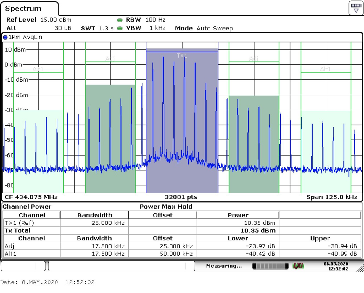
We have designed an RF beacon using the CC110L device which gives audible 'beeps' on our hand held receiver (an off the shelf item).  It has been tested to ETSI EN 300 220-1 and has failed the Adjacent Channel Power test when in it's normal mode of operation, which I understand equates to the D-M3 test signal.

The test results are 

The test limit for the adjacent channel is -37dBm.

The balun and filter components are as per the 433 MHz reference design and the 26 MHz crystal meets the datasheet requirements.  The antenna is a length of wire cut to one quarter wavelength.

We previously attempted to provide a better match to the antenna, but did not see any performance benefits, so the design was left as per the reference design.

The transmitter is set up as follows

  • Base Frequency - 434.074951
  • Modulation Format - 2-FSK.
  • Data rate - 7.38907kHz
  • Transmitted Data - 10101010101010.....10
  • TX Power - 10dBm
  • TX Pattern - ~100ms on, ~100ms off, ~100ms on, ~2000ms off, repeat

I am looking for any advice on how to fix this issue.  Are there any adjustments available within the CC110L that can reduce the Occupied Channel Width from 25kHz to <20kHz, where the test limits are higher?

Would a different modulation scheme help?

Unfortunately, with the spectrum analyser I have, I have been unable to re-create the trace shown above.  For example, with the RBW at 100Hz (as per the test spec), the analyser is only happy with the sweep time set at 50 seconds.  The sweep time at the test house appears to be only 1.3 seconds.

Any advice would be greatly appreciated.

Thanks

Paul


  • From the standard: "D-M3: A test signal representative of normal operation of the EUT.".

    It looks like you are basically sending preamble which will generate this pattern with a lot of peaks you are seeing. 

    Also, the standard does not require you to test with TX on/ off, in fact you should test with a continuous TX to test according to ETSI EN 300 220-1.

    Meaning that your first course of action is to ensure that you are actually are testing according to the standard. 

  • Thanks for your quick reply.

    I believe the unit is running it's standard firmware, which is why the Tx is on/off - that is it's standard mode of operation, but your point about preamble is an interesting one.

    I will speak with my colleagues and discuss whether the firmware in the test unit needs to be tailored to make it more suitable for the test being undertaken.

  • Hi TER,

    I passed your comments on to the firmware engineer that did the builds for the test house.

    Here is his reply:

    The tests (specifically the on/off part) were specified by the test house. 
    We are sending 1's and 0's just so that we get an audible signal - there is no specific reason to using this pattern over any other. If we were sending actual data over an FM link, the data would be variable anyways. Perhaps having the data oscillate less causes less harmonics? In which case we can try having the data as 11001100....1100 instead of the current 101010101...01 (or some other variation).
    Do you think changing the data will significantly impact the result?
    Thanks
     
  • Could you first test using SmartRF Studio and select: Continuous TX, modulated, random mode?

    Also try using GFSK instead of FSK since the spectrum for GFSK has lower side lobes. 

  • Hi TER, I will speak with the firmware engineer about this.

    Incidentally, I checked with them and all the firmware/modes of operation for the testing was agreed with the test house prior to sending the device to them.