This thread has been locked.

If you have a related question, please click the "Ask a related question" button in the top right corner. The newly created question will be automatically linked to this question.

CC1110-CC1111: CC1110 - Active Mode Current Consumption

Part Number: CC1110-CC1111
Other Parts Discussed in Thread: CC2510

Hello,

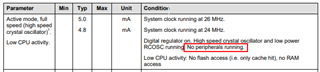
I am using CC1110 for Wireless Temp. Humidity Sensor Application. Currently I am working on power budgeting. The measured active mode current is 6.8 mA against 5 mA mentioned in the datasheet.

Can anyone please help with minimum and maximum current values?

I have tested with multiple hardware module with and without peripherals. Active mode current is constant 6.8 mA. In reception also, the current is up by almost 2 mA as against the datasheet.

Please help 

  • Hi,

    Do you measure with an antenna connected or a 50 ohm port?

  • Yes. With Antenna Connected

  • Hi,

    Can you measure with a pure 50 ohm load ?

    The current consumption can change slightly depending on the exact antenna match / impedance.

  • Ok. I will measure. Can you please tell on what lines you are thinking? There are DC blocking capacitors in series with RF_P and RF_N pins. So I don't think current will pass. Should I remove series capacitors for RF_P and RF_N from board?

  • Hi, the dc capacitors can still be mounted. Perform the DC current consumption measurements when the RF is connected to a broadband 50 ohm source. e.g. spectrum analyzer, 50 ohm load SMA connector or two parallel 100 ohm resistors to GND. 

    The current consumption will change pending the impedance so by having a solid reference impedance of 50 ohm; then it is easier to compare the current consumption numbers.

  • Hi, we connected 50 ohm load SMA connector. But it is still the same 6.8 mA. Active mode current consumption mentioned in datasheet is based on which considerations ? We measured current consumption of CC2510 also which is 4.8 mA in datasheet but in practice it is coming as 6.5 mA. Is it normal or there is some issue?

  • Hi,

    The datasheet figures are based upon measurements from the validation test system so there is no modification of the results presented in the datasheet. If the datasheet states a figure, then this value should be measured by you as well for the same conditions.

    If the antenna impedance if far from 50 ohm, then the current consumption can change. In your case, the results are similar with antenna connected or with a 50 load connected. This is good that the results do no differ but does not identify the root cause of the extra current consumption that you are seeing.

    Is your supply 3.0V ?

    26 MHz crystal ?

    What current consumption do you measure for the other Power Modes [0 to 3] ?

    Can you post the RF section of the schematic ?

  • HI,

    1. The supply is 3.0V

    2. Crystal is 26 MHz

    3. PM2 mode power consumption is 0.8 uA - 1 uA 

    4. RF Section

  • The measured active mode current is 6.8 mA against 5 mA mentioned in the datasheet.

    As stated in the datasheet the active power consumption will be dependent on the CPU activity and what else is active on the chip while doing this measurement. 

    Could you share how you have setup the chip when doing this measurement? 

  • Hi,

    The chip has a temp. and humidity sensor attached to it over SPI. But the sensor is in shut down mode. Below are the some current measurement.

    PM2 Mode 1.6 uA
    Active Mode (Sensor - Power Down) 6.57 mA
    Active Mode (Sensor - ODR 12.5Hz) 6.89 mA
    Avg Transmission Current(+10 dBm) 24.6 mA
    (+5 dBm) 20 mA
    (0 dBm) 18 mA
    Continuous Reception 25 mA

    Lot of discrepancies against the datasheet. Transmit Current is OK as there is a delay in between. The issue is with reception and active mode current

  • From the datasheet:

    Not sure if the SPI will increase the power consumption. If you want to compare with the datasheet, ensure that no peripherals are used. 

  • Hi TER,

    There is one issue I am facing with SPI current consumption. The temp. & humidity sensor is connected to CC1110 with SPI. When the sensor is activated, the peak current consumption is reaching 360 uA whereas the peak sensing current mentioned in the sensor datasheet is 60 uA. I have configured SPI pins as peripherals. Is it possible that current will leak from SPI pins given that 20 Kohm pull up is connected on SPI pins ?

  • Hi,

    Disconnect all the peripherals from CC1110 in order to measure the current consumption of CC1110

    If the datasheet of the sensor is 60 uA_max and you are measuring 360 uA, then there is definite current leak somewhere. Have you measured the current consumption of the sensor with and without the SPI lines connected?