This thread has been locked.

If you have a related question, please click the "Ask a related question" button in the top right corner. The newly created question will be automatically linked to this question.

swrr092 cc1120+cc1190 reference design, impedance control

Other Parts Discussed in Thread: CC1120

Hi,

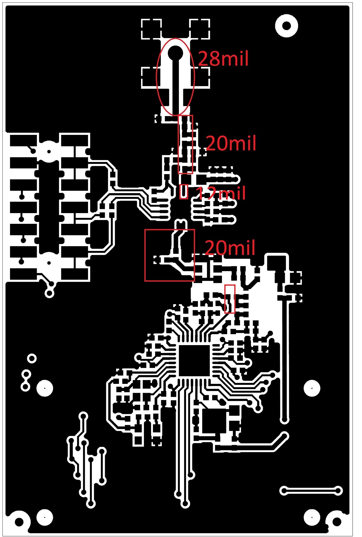
We are fabricating a RF board based on cc1120+1190 reference design. However, we found out that there are different trace width for the RF path, 28mil, 20mil, 12mil etc, as shown in the attached gerber pic.

Could you share with us what impedance shall we follow? so as to have highest transmit power, and best sensitivity.

Do we need to have impedance control for the entire PCB or just the RF traces?

Appreciate your advice.

Thanks and regards,

Shanguo

  • This is a question that has been answered fairly often on the forum.

    The lines in question are short. A line that is shorter than about 1/10 of the wavelength will not behave as a transmission line and hence using a stripline calculator will not give the correct result.

    Also, only the line towards the SMA connector should be 50 ohm, the impedance in the other pins are far from 50 ohm.
  • Thanks TER for your quick response.

    So in this case, only the 28mil is 50ohm, but that line (~1cm) is much shorter than 1/10wavelength (~3cm). Do I need to keep that transmission line as long as possible? That will impact the PCB board size.

    I am actually trying to follow  the reference design very closely. However, I am replacing the whip antenna with a single core copper wire, I can't afford to have that huge whip in my small embedded device. Will there be any foreseeable issue? The transmission line to the wire antenna is short.

    It was mentioned in another post that ADS is recommended to make sure the impedance is met, that is referring to tuning of capacitors/inductors? Not the trace width right.

    As said earlier, I'd like to have best output power and receive sensitivity.

    Sorry, I am not very familiar with RF circuit design.

    Thanks and regards,

    Shanguo

  • An option to a copper wire is a PCB antenna like www.ti.com/.../swra416.pdf

    For the trace out to the antenna, keep the width and make it as short you need to to connect to the antenna of your choice.

    ADS is used to simulate the layout together with "real" components (s-parameter models from the passive component manufacture)
  • Thanks.

    I don't have real estate to incorporate the PCB antenna (at least +10mm length). But for wireless sensors, sometime it is okay to have a thin wire in the air.

    regards,
    Shanguo
  • If you use a wire antenna that is possible for a user to touch look into adding some ESD protection on the antenna node.