This thread has been locked.

If you have a related question, please click the "Ask a related question" button in the top right corner. The newly created question will be automatically linked to this question.

CC1310 with SKY65313-21 FEM and 0850BM14E0016 balun @868MHz

Other Parts Discussed in Thread: CC1310

Hi,

I would like to developed a gateway with CC1310 which has good sensitivity and good transmit power. I'm planning to use antenna diversity as well. I will try to implement my gateway with 0850BM14E0016 balun and with SKY65313-21 FEM.

What should be the settings for CC1310 and could you please check my schematics?

Best Regards

Cem

  • - Settings: we have not looked at this combination.
    PA table: You have to create your own PA table. Since we don't have a reference design using the skyworks part we don't have a recommended table
    RSSI offset: The RSSI offset will be slightly different when adding a LNA.

    - We can check your schematic.
  • Dear TER,

    our application is to collect presence of a car from parking lots using sensors located under the cars and buried just under the asphalt. We decided to use 434MHz for our application due to poor radio reception on 868MHz.

    The sensors should be battery operated and they will not have any power amplifier etc on board.

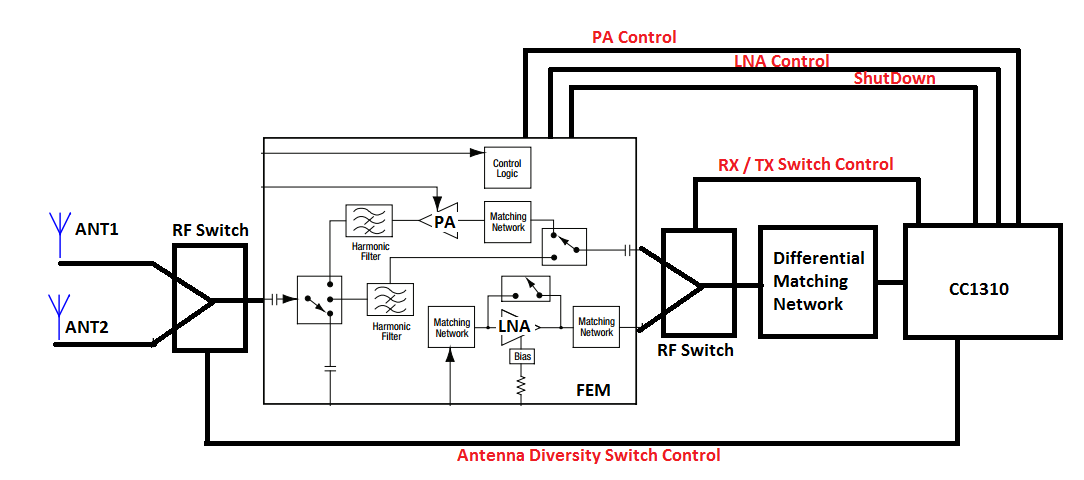
    Therefore the receivers should have a very good receiver sensitivity. We are planning to use differential operation with external bias to get maximum receiver sensitivity. We also are planing to use SKY65366-21 with antenna diversity to increase range for our sensors. Before starting to schematics, we would like to be sure about our high level design. You can see our high level design as below.


    We are a bit confused on how to control several DIOs like RF switches and PA, LNA etc. We see some documents explaining antenna diversity like swra523. Here are our questions:

    1- Is it possible to route IOC_PORT_RFC_SMI_CL_OUT (0x37) signal to any pin to control Antenna Diversity Switch explained in swrc325 sample codes? 

    2- In user manual of CC1310 (swcu117f), it is stated that LNA and PA can be controlled using RFC_GPO0 and RFC_GPO1. (11.3.2.1 Control External LNA/PA (Range Extender) With I/Os) I need LNA to be active low. Is it posibble to use IOCFGX register IOMode fields (26-24 bits) INV  get a active low operation for LNA?

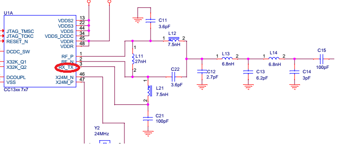
    3- Should I use RX / TX pin of CC1310 RF Switch control just before FEM? We see that the RX/TX pin is used for external biasing in differential matching in  CC13xxEM-7XD-7793_4L design like below? Is it posible to other pins for controlling this switch?


    4- Can you please comment on our high level design? 

    Best Regards

    Cem

  • 1) Not sure if I understand the question. Page 6 in www.ti.com/.../swra523.pdf explains how to map IOC_PORT_RFC_SMI_CL_OUT to the pins you want to use. This is step 2 on page 6.

    2) This can be done with the pin driver. Step 3 on page 6 in the app note shows how to invert a signal in the pin driver.

    3) The RXTX pin is not a control signal, it's to bias the LNA. You have to use a separate DIO to control the switch.

    4) First of all, could you please elaborate a bit more why you selected 433 MHz compared to 868 MHz? On 433 MHz the max output power is typically limited by regulations. Why do you think 433 MHz will work better? How is the antenna placed in this case?
  • Dear Ter,

    the first 3 questions are for verifying our understanding. Thanks for reply.

    The last one is our major issue here. We thought that using lower frequencies help us to send data further assuming the same transmit power applicable. Unfortunately, you are right.

    The antenna will be placed vertical to ground. I have used the indoor/outdoor range estimation excel sheet, but I do not know how to model a  sensor node placed under a car and just 2-3 cm away from the ground.

    Best Regards

    Cem

  • An effective antenna is a challenge for this use case since the antenna will be close to a large ground plane. Here it's important to find an antenna type that is as effective as possible when close to a large ground plane.

    For the range estimation tool you get an indication if you type in the real height. But it's also dependent on the material if it behaves like a ground plane or not. For this type of application I would recommend some field tests to find out the range when you have the antenna close to the ground plane and a parked car.
  • Thank you Ter for your suggestions. I will post our range tests results.

    Best Regards

    Cem

  • Dear TER,

    I would like to share schematics to be checked by you as we discussed before. Should I sent email to you?

    Best Regards

    Cem

  • Hi,

    TER is currently Out-of-office.

    Can you post the schematics or send them to me so I can review them ?

    Regards,

       Richard

  • Send a friend request to one of us and we can take a quick look.