This thread has been locked.

If you have a related question, please click the "Ask a related question" button in the top right corner. The newly created question will be automatically linked to this question.

CC1200: Rx performance Sensitivity

Part Number: CC1200

Hi,

we are using a CC1200 on a personal board and we are testing sensitivity. We have a sensitivity of -106dBm on this board and with CC1200EM too, but we expected a better result. 

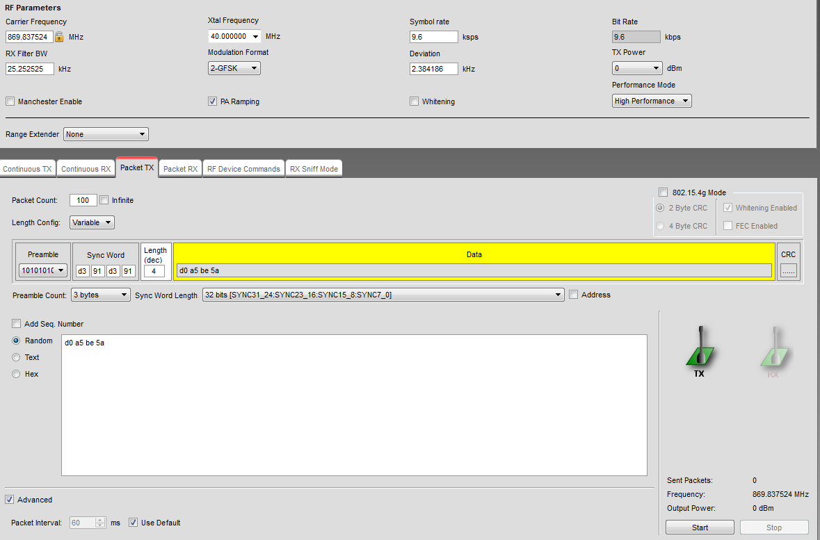
We are using the following parameters :

9,6kbps, 2-GFSK, DEV = 2,4kHz, RX filter BW = 25kHz

Does that seem correct to you or our results can be improve?

Thanks,

Quentin.

  • How do you define sensitivity limit? Is it 1% BER? Or is it a PER number? If yes, what is the payload length?

    Theoretical sensitivity is -174 dBm + NF + 10log(RX BW) + SNR. With NF = 7 dB, RX BW = 25 kHz and SNR = 10 dB the 1% BER sensitivity would be close to -113 dBm.
  • We use a CC1200 EB in Tx with Smart RF, after we have a personal PCB to add attenuation and in Rx we have our PCB with CC1200.

    We send a known number of packets with Smart RF and with our board via UART we can see the number of packets received.

    Here a screenshot of Smart RF config :

    Thanks,


    Quentin.

  • Based on the SmartRF Studio picture you use 4 byte payload. 1% BER then corresponds to PER = 27.5%. I would expect the 1% BER to be around -113 dBm for a proper design. 

    What you can do is to measure the noise floor. Do the following: Leave the TX off. Read the RSSI with no signal at the antenna. Assuming 10 dB SNR for 1% BER the sensitivity should be 10 dB above the noise floor. If the noise floor is significantly higher than approx -123 dBm there might be an issue with your PCB design.

  • At one point I tested the measurement method you are describing and it is hard to get the correct numbers due to:
    - You need to know the exact output power on the Tx side
    - You need to know the exact attenuation. My experience was that the attenuation could be different than what I programmed due to insertion loss and so on.
    - You need to shield you RX side. Some energy will be emitted by the TX side over the air and if the RX side is not shielded it could pick up some of this energy (but it could be that this will be phase shifted)
  • We measured noise floor first with CC1200 EM & TrxEB with smart RF (continuous Rx so we can see RSSI directly) and indeed we have value around -123dBm.

    When we try with our board, method is different because we can't use Continuous RX window, we used a function where we read the RSSI register and our results are between -110dBm and -120dBm. So we checked Vcc of our board and compared it to CC1200 EM and the signal looks the same so power supply doesn't seem to be the problem.

    Then we disconnected CC1200 on our board and connect CC1200 EM with SPI to our µP and we have the same results than with our personal board.

    So our questions are :

    - a difference on the SPI signals (between Eval Board and our board) can make a difference on the measurement?

    - Or measurement method with RSSI register is not a reliable method if we compare it to Smart RF studio?

    Thanks,

    Quentin.
  • If I understand you correctly you have implemented you own "Continuous RX" on you MCU and you connect this MCU to both you board and a CC1200 EM and get the same result.

    For this test is the settings the same as you use in the Continuous RX test with SmartRF Studio (do a register export and use directly in your code)?

    To my knowledge SmartRF Studio polls the RSSI register so it shouldn't be any difference in method.