Other Parts Discussed in Thread: CC1190, CC1101
Tool/software: Linux
Hello! I designed a PCB based on your demo PC1101_CC1190EM 869MHz rev 2.1.0. I check on the spectral analyzer and do not really understand what is happening. There may be an error in the code when switching reception and transmission.
The board is not directly connected to the spectrum analyzer.
The board is installed on Raspberry Pi 3, using wiringPi SPI.
Software based on your Link2 example.
Base frequency: 869.524780 MHz
Xtal Freq: 27MHz
Data rate 38.4178 kBaud
Channel spacing: 207.641602 kHz
RX Filter BW: 105.468750 kHz
Deviation: 19.775391 kHz
Modulation: GFSK
TX Power (PA Table): 0xC0
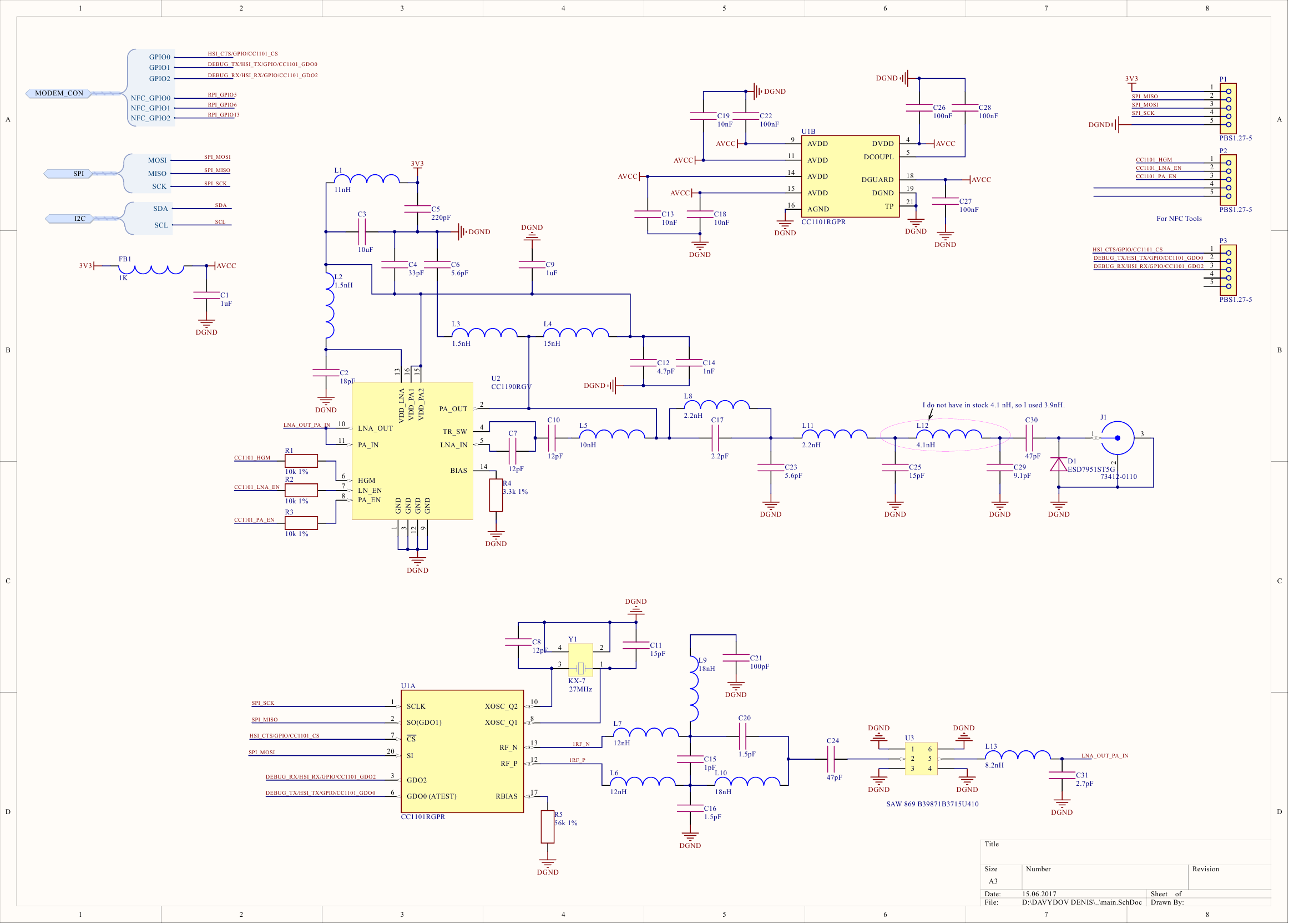
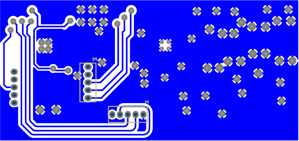
Scheme
PCB 2-Layer
TOP Layer
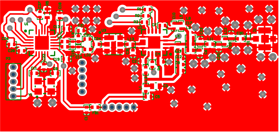
BOTTOM Layer
Setting
uint8_t register_set_value[47] =
{
     0x07,  // IOCFG2              GDO2 Output Pin Configuration
    0x2E,  // IOCFG1              GDO1 Output Pin Configuration
    0x06,  // IOCFG0              GDO0 Output Pin Configuration
    0x0E,  // FIFOTHR             RX FIFO and TX FIFO Thresholds
    0xD3,  // SYNC1               Sync Word, High Byte
    0x91,  // SYNC0               Sync Word, Low Byte
    0xff,  // PKTLEN              Packet Length
    0x44,  // PKTCTRL1            Packet Automation Control
    0x05,  // PKTCTRL0            Packet Automation Control
    0x00,  // ADDR                Device Address
    0x00,  // CHANNR              Channel Number
    0x06,  // FSCTRL1             Frequency Synthesizer Control
    0x00,  // FSCTRL0             Frequency Synthesizer Control
    0x20,  // FREQ2               Frequency Control Word, High Byte
    0x34,  // FREQ1               Frequency Control Word, Middle Byte
    0x62,  // FREQ0               Frequency Control Word, Low Byte
    0xCA,  // MDMCFG4             Modem Configuration
    0x75,  // MDMCFG3             Modem Configuration
    0x13,  // MDMCFG2             Modem Configuration
    0x42,  // MDMCFG1             Modem Configuration
    0xF8,  // MDMCFG0             Modem Configuration
    0x34,  // DEVIATN             Modem Deviation Setting
    0x07,  // MCSM2               Main Radio Control State Machine Configuration
    0x30,  // MCSM1               Main Radio Control State Machine Configuration
    0x28,  // MCSM0               Main Radio Control State Machine Configuration
    0x16,  // FOCCFG              Frequency Offset Compensation Configuration
    0x6C,  // BSCFG               Bit Synchronization Configuration
    0x03,  // AGCCTRL2            AGC Control
    0x40,  // AGCCTRL1            AGC Control
    0x91,  // AGCCTRL0            AGC Control
    0x87,  // WOREVT1             High Byte Event0 Timeout
    0x6B,  // WOREVT0             Low Byte Event0 Timeout
    0xFB,  // WORCTRL             Wake On Radio Control
    0x56,  // FREND1              Front End RX Configuration
    0x10,  // FREND0              Front End TX Configuration
    0xE9,  // FSCAL3              Frequency Synthesizer Calibration
    0x2A,  // FSCAL2              Frequency Synthesizer Calibration
    0x00,  // FSCAL1              Frequency Synthesizer Calibration
    0x1F,  // FSCAL0              Frequency Synthesizer Calibration
    0x41,       //RC Oscillator Configuration
    0x00,       //RC Oscillator Configuration
    0x59,        //Frequency Synthesizer Calibration Control
    0x7F,         //Production Test
    0x3F,       //AGC Test
    0x81,  // TEST2               Various Test Settings
    0x2D,  // TEST1               Various Test Settings
    0x09  // TEST0               Various Test Settings
};
Switching to transmission:
cc1101_StrobeCmd(SIDLE);
cc1101_StrobeCmd(SFTX);
cc1101_Write_BurstAccess(TX_FIFO, txBuffer, LENGHT_LENGHT_FIELD + txBuffer[0]); //DATA_LENGHT + CRC_LENGHT + LENGHT_LENGHT
cc1101_StrobeCmd(STX);
Switching to reception:
cc1101_StrobeCmd(SFTX);
cc1101_StrobeCmd(SIDLE);
cc1101_StrobeCmd(SFRX);
cc1101_StrobeCmd(SRX);
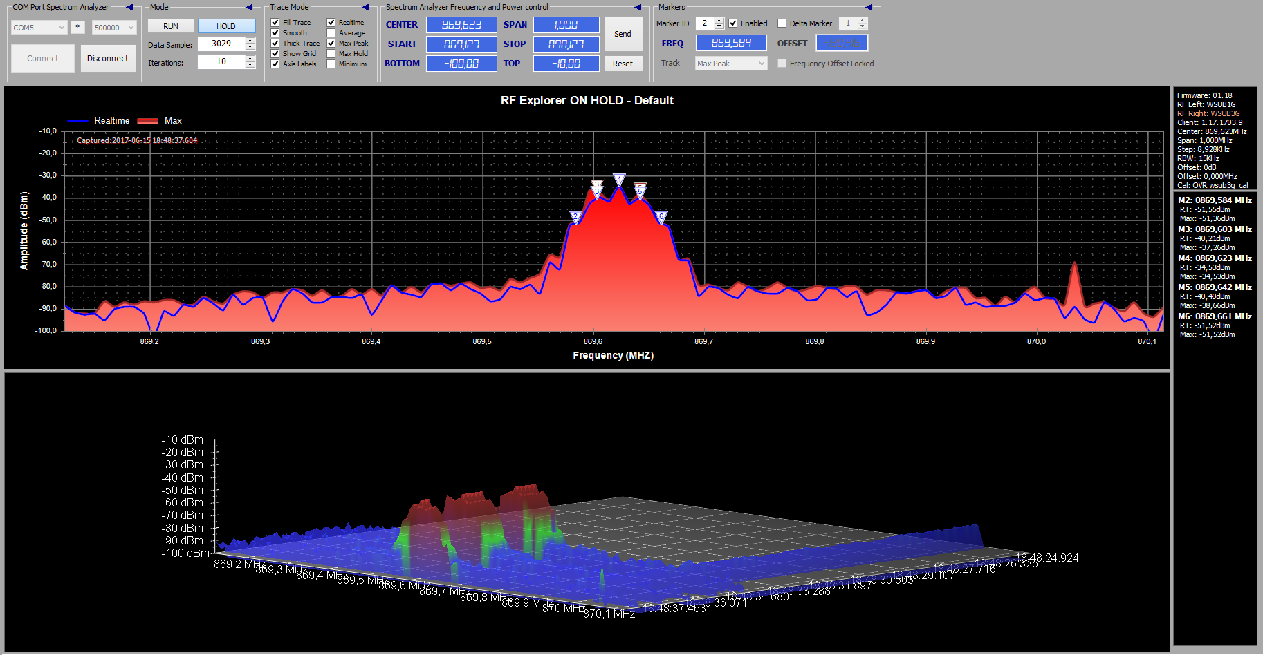
The transmission attempt is 5 times. On the screenshots of the spectral analyzer, you can see five transmissions. Why such a spread in frequency?
First send
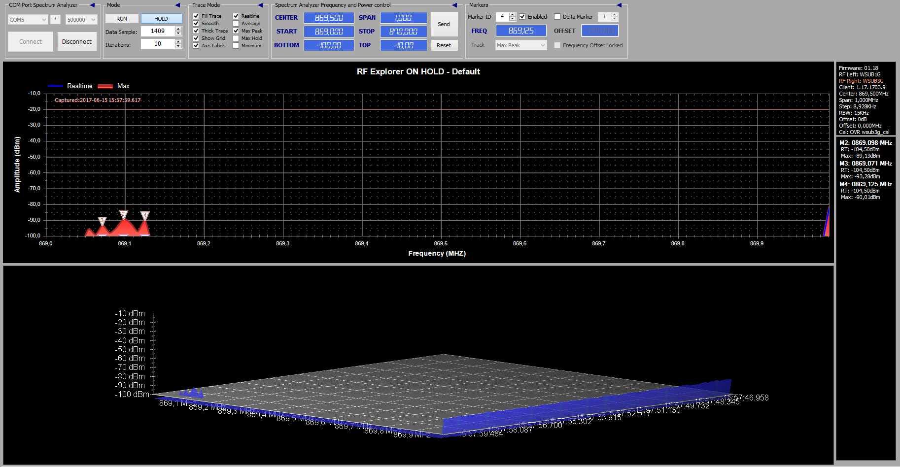
Second
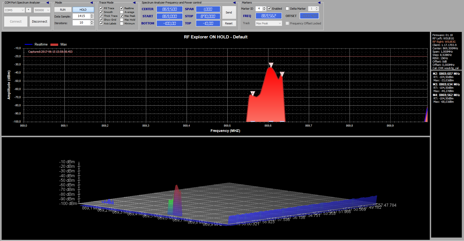
3
4
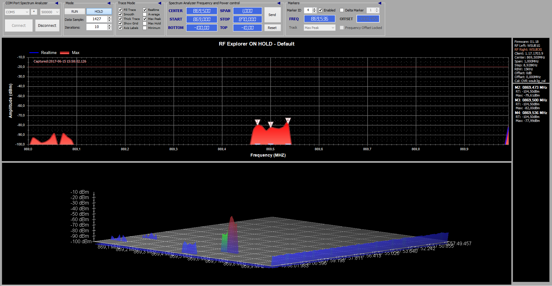
5

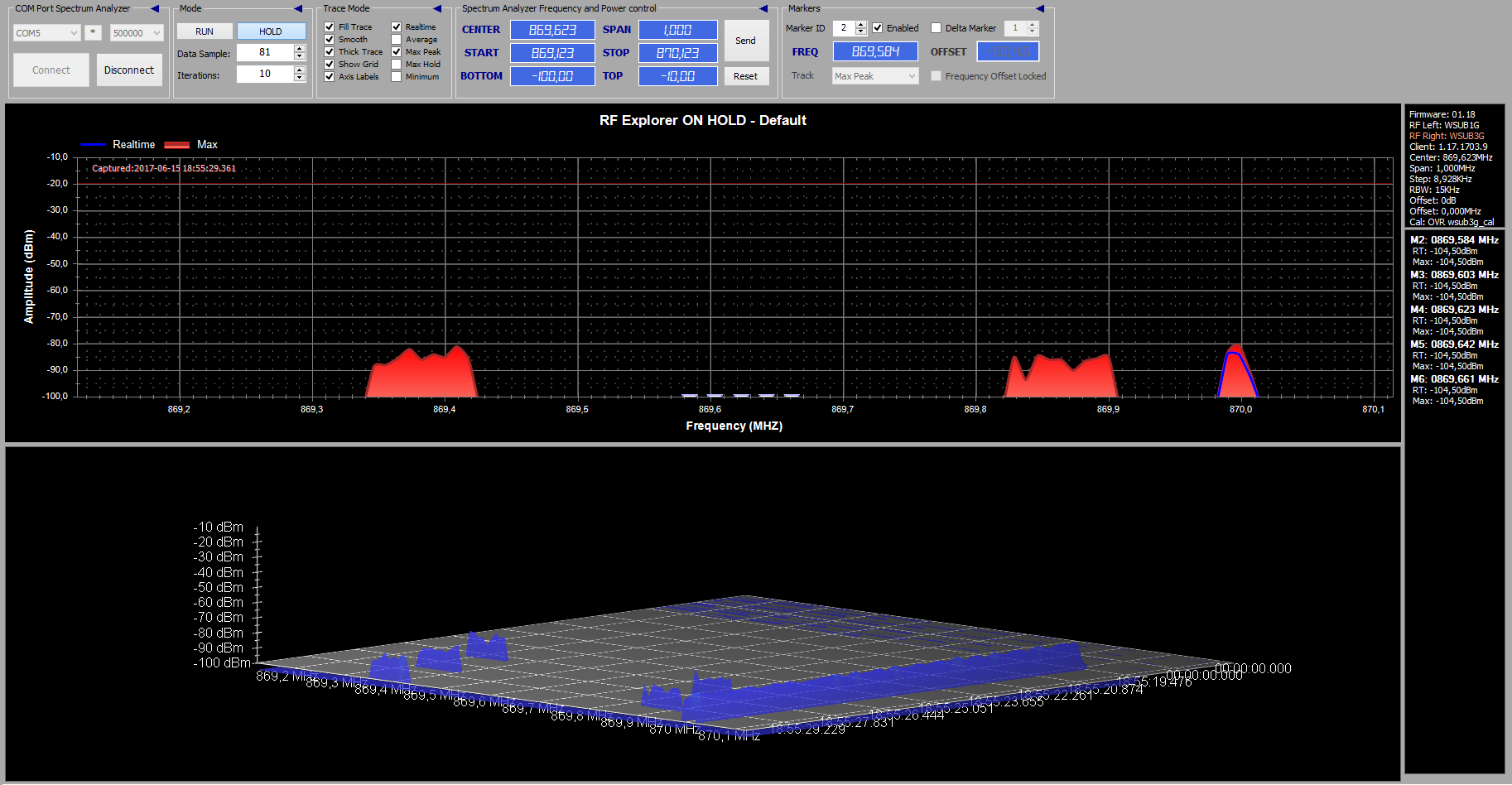
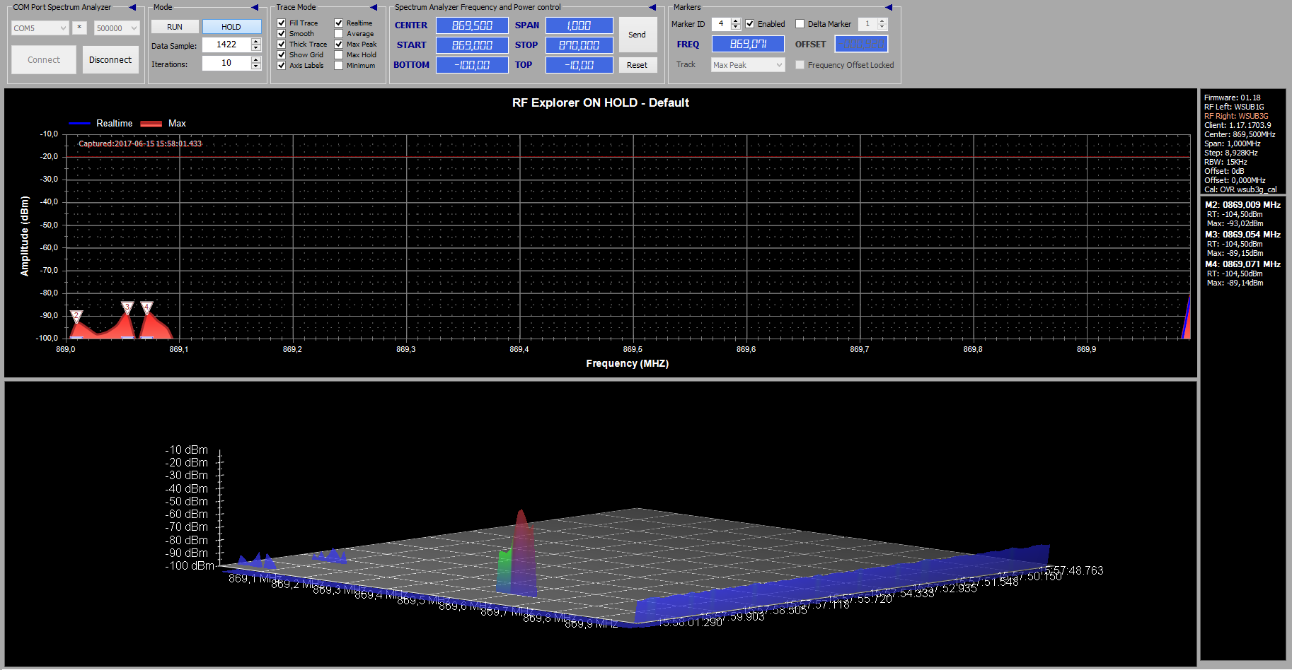
If you add a calibration before switching transitions, that is, like this:
Switching to transmission:
cc1101_StrobeCmd(SIDLE);
cc1101_StrobeCmd(SCAL);
cc1101_StrobeCmd(SFTX);
cc1101_Write_BurstAccess(TX_FIFO, txBuffer, LENGHT_LENGHT_FIELD + txBuffer[0]); //DATA_LENGHT + CRC_LENGHT + LENGHT_LENGHT
cc1101_StrobeCmd(STX);
Then the picture of the spectrum changes. I have not yet checked for data reception, but I'm still wondering if this is the correct behavior of the transmitter.
Here are all 5 transmission attempts.

How to properly switch between receiving and transmitting and correctly adjust the chip?