This thread has been locked.

If you have a related question, please click the "Ask a related question" button in the top right corner. The newly created question will be automatically linked to this question.

CC115LEM-868-915-RD: Existence of CC115L Daughterboard for TrxEB Board

Part Number: CC115LEM-868-915-RD

Hello,

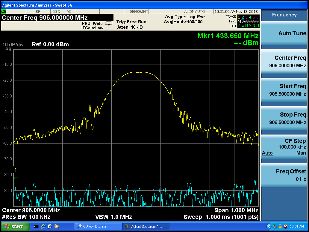
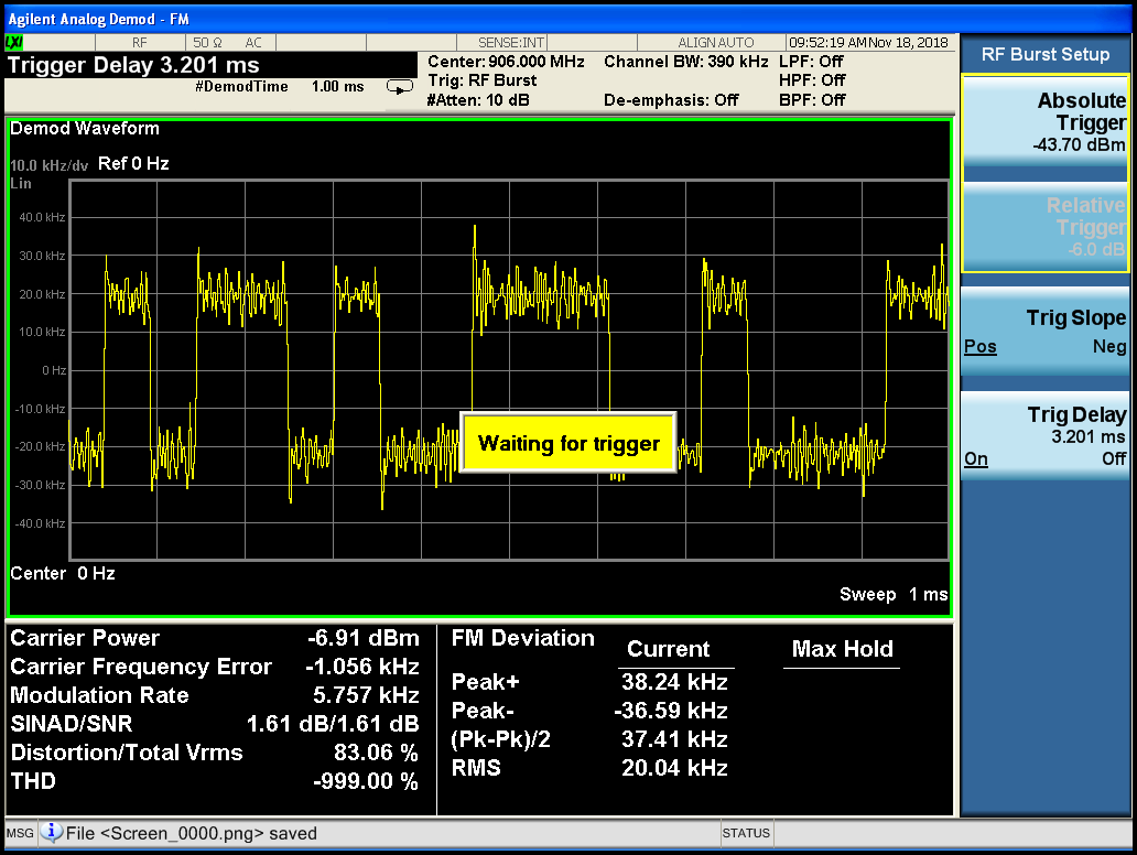
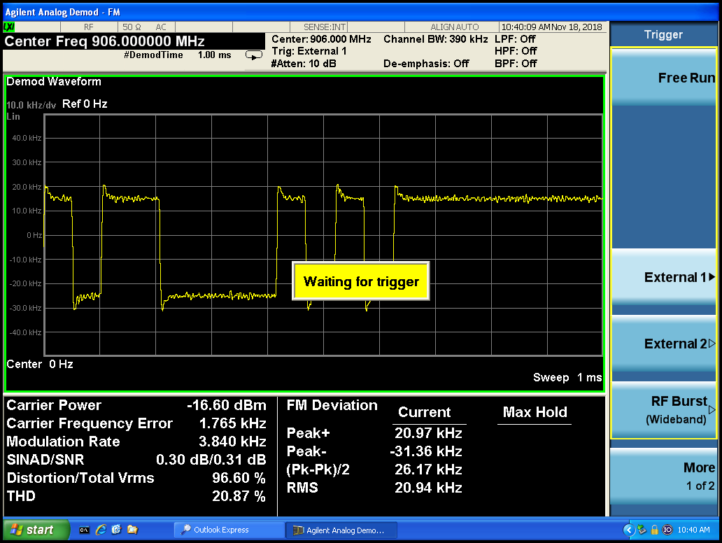
We have a product on hand (whose source code we cannot access) that uses the CC1120 radio, and for one of our commissioned products we've had to adapt these radio settings to the CC115L, which we're also using in several other products. However, when we use a 2-FSK modulation scheme for our transmissions, we're seeing a lot of modulation noise that isn't present in the CC1120 radio.

To determine if a the hardware issue or our software register settings, we're looking for a CC115L daughterboard that we can plug into the TrxEB boards. After doing some research, it looks like TI used to manufacture a development kit (CC11XLDK-868-915) that included the CC115L eval board. Unfortunately, it's now obsolete and unavailable from any third-party suppliers. Is there any replacement development kit for the CC115L?

Thanks,

Jennifer

  • I have to check why it looks like a CC115L EM is not available.

    What you can do is to the a CC1101 EM and test with this. CC1101 is a superset of CC115L and will have the same RF performance if you use the same settings.

    When you are testing your CC1120 based radio and the CC115L , do you use the same settings when you compare the modulation?

    Could you provide some plots of what you are seeing?
  • Thanks for the suggestion--if there's no way we can get a CC115L EM then we'll try a CC1101 EM as a last option.

    Power level of the radio is slightly different (programmed for 15dBm on the CC1120 and for 12dBm on the CC115L) but basic settings like modulation scheme (2-FSK), frequency (906MHz), deviation, data rate are the same. We verified that our trigger point on the "noisy" units were valid by looking at the spectrum:

    Here was our reference signal from an RF signal generator:

    Here's the CC1120 transmission:

    And here's one of the CC115L units (the other looks similar):

    Here was the CC1120 EM board on the TrxEB, using the same radio settings as the "clean-looking" transmission on the CC1120 above:

    We've ruled out the crystal on our "noisy" CC115L hardware by substituting it with a 26MHz reference signal, and we've improved the GND plane connectivity on our PCB in one questionable section, but this didn't make a difference. We think it could be the frequency synthesizer calibration settings, but would like to determine if the TI-approved hardware might demonstrate similar capacity for noise. We do use the SCAL strobe command after transmitting. Any suggestions would be helpful.

    Cheers,

    Jennifer

  • Could you share the settings you are using on CC115L and with this plots, do you use the FIFO or input on a pin?
  • We're using the FIFO on these plots.
    Settings are
    {CC115L_IOCFG2, 0x2E},
    {CC115L_IOCFG1, 0x2E},
    {CC115L_IOCFG0, 0x06},
    {CC115L_FIFOTHR, 0x47},
    {CC115L_SYNC1, 0xD3},
    {CC115L_SYNC0, 0x91},
    {CC115L_PKTLEN, 0x16},
    {CC115L_PKTCTRL0, 0x04},
    {CC115L_FSCTRL0, 0x00},
    {CC115L_FREQ2, 0x22},
    {CC115L_FREQ1, 0xD8},
    {CC115L_FREQ0, 0x9C},
    {CC115L_MDMCFG4, 0xF9},
    {CC115L_MDMCFG3, 0x83},
    {CC115L_MDMCFG2, 0x03},
    {CC115L_MDMCFG1, 0x42},
    {CC115L_MDMCFG0, 0xF8},
    {CC115L_DEVIATN, 0x34},
    {CC115L_MCSM1, 0x30},
    {CC115L_MCSM0, 0x18},
    {CC115L_RESERVED_0X20, 0xFB},
    {CC115L_FREND0, 0x10},
    {CC115L_FSCAL3, 0xE9},
    {CC115L_FSCAL2, 0x2A},
    {CC115L_FSCAL1, 0x00},
    {CC115L_FSCAL0, 0x1F},
    {CC115L_RESERVED_0X29, 0x89},
    {CC115L_RESERVED_0X2B, 0x63},
    {CC115L_TEST2, 0x81},
    {CC115L_TEST1, 0x35},
    {CC115L_TEST0, 0x09},
    {CC115L_PARTNUM, 0x00},
    {CC115L_VERSION, 0x09},
    {CC115L_MARCSTATE, 0x00},
    {CC115L_PKTSTATUS, 0x00},
    {CC115L_TXBYTES, 0x00},
  • Where comes the value for CC115L_RESERVED_0X29 and {CC115L_RESERVED_0X2B from?

    Is it only when you demodulate the FSK signal as you do here that you see this noise?

    If you send a CW or a modulated signal with random data with a very low RBW, do you see that the frequency change?
  • 0x29 and 0x2B values came from SmartRF studio.

    As I am somewhat of a novice in RF engineering, I'm not sure what you mean by "only" when we demodulate FSK. Please correct me if my following description does not answer your question: we haven't observed any similar noise when demodulating ASK, for instance, but I'm unsure of whether this noise would show up on the spectrum analyzer.

    We do not see the frequency change with low RBW on our measurement device. One of the units is slightly off-frequency due to our xtal tolerance spec (+10kHz or so off from center 906MHz), but the noise level stays the same.

    In another of our products that uses the CC115L radio at 906MHz with 10kHz deviation, we see the demodulated signal scaled to the +/-10kHz points, but with the same bandwidth of modulation noise observed in the noisy units shown previously.

  • Forgot to ask: Does the noise you see cause any issues? Why are you looking into this?

    WHen I check SmartRF Studio for registers 0x29 and 0x2B I get different values than the ones you have used.
  • I'm looking into this as a mixture of personal curiosity as to why (or if) the radios would behave differently as well as a company interest in possibly improving the RF range. Previous work has included device verification testing (including range tests) and we are happy with its "macroscopic" behavior, so this issue is not holding up our production, but we have not previously looked at the demodulation of this signal. Our goal is to strive to make the best product we can, so if this noise can be resolved by a simple register or code change then we think it's time well-spent.

    Do you happen to know if those might be critical registers that could affect demodulation noise; and, if so, what are the values you see in the SmartRF studio?

  • I get the following:

    Not sure what the registers do, if anything, but please use the values given by Studio.

    I'm also not sure how much the demodulated signal on the spectrum actually tell about the signal quality. I would look at the spectrum directly to verify

  • Not clear why my suggested answer was rejected.
  • Hello,

    We're still looking into the issue because the noise problem is not yet resolved. Do you happen to have any answer as to why the CC115L evaluation kit is not available through primary distributors at this time?

    I found a couple of third-party sellers on eBay; they're in the UK and France. None in the US, as far as I can tell.

  • I suspect that the CC115L kit is not sold anymore due to low volume.

    Have you looked at the spectrum from CC115L without decoding the data but with a low RBW?
  • Yes, we looked at the spectrum and did not find anything of major concern (it triggered OK). Thank you for the answer on the CC115L radio eval kit availability.