This thread has been locked.

If you have a related question, please click the "Ask a related question" button in the top right corner. The newly created question will be automatically linked to this question.

CCS/LAUNCHXL-CC1310: CC1310 Re-shape PA ramp

Part Number: LAUNCHXL-CC1310
Other Parts Discussed in Thread: CC1310, , CC1350, CC1352P, CC1352R, CC2650

Tool/software: Code Composer Studio

HI, we need to control PA ramping in CC1310.

i read the linker:

but i still can't understand "How exactly the registers 0x608C and 0x6088 work together to define PA ramp time".

does anyone can explain that or give me a doc?

Thanks

LN

  • We need to reduce these noises and what is the right way to do it ?


    Thanks!
    LN
  • Hi,

    The other post you are referring to already has information about TX output power configuration with IB and GC controls and the connection between values in 0x6088 and 0x608C registers to these controls. I am not sure what other information you are looking for, can you please explain.

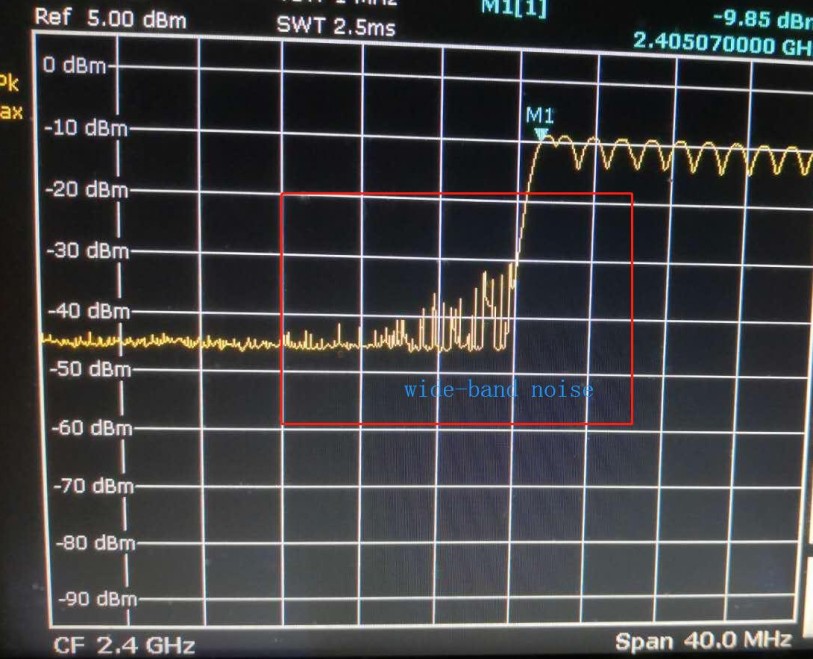
    What is the datarate you are planning to use? From the spectrum capture, it looks like PA ramping has been enabled already. is this being tested on custom hardware?

    Regards,

  • Hi SVS,

    I test it on SimpleLink CC1310 LaunchPad kit (LAUNCHXL-CC1310) .

    datarate is 100K.

    i cannt understand how to get the ramp time accprding to the linker(i can't open the linker:http://processors.wiki.ti.com/index.php/Settings_for_Different_PHY%27s)

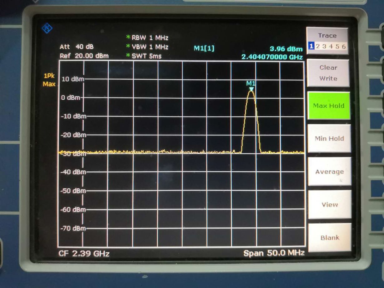
    please refer to the picture, what i want  is to depress the wide band noise,What shall I do?

    Thanks!

    LN

  • Hi,

    CC1310 is a device for sub-GHz band only. Can you please clarify if you are using CC1350.

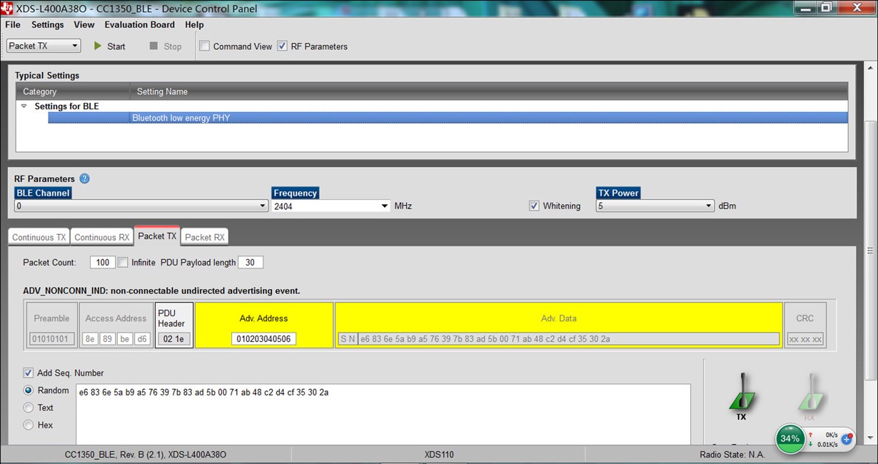
    Also, please share the config file from smartrf studio or smartrf settings file for complete radio configuration so I can replicate this on my test setup.

    Regards,

  • Hi,

    yes, it is CC1350,i just use the SmartRF Studio 7 like this:


    Thanks!

    LN

  • Is the "noise" you have marked within the red square a issue? In other worlds, do you have trouble complying to the regulations where you operate? 

  • yes, it is a serious issue for us.

    we need to incress the output Power to 20dbm(add a external PA between the output of CC1350 and antenna).

    The problem arises:when the Tx Power incress to 20dbm(2404MHz),the noise(Official name "transient spurious") incress to about -10dbm(at freq 2400MHz) which is irregular(FCC/EU/MIC...)

  • Have you considered CC1352P that has a 20 dBm PA? 

  • Hi,

    i have tested the CC1352P, it works well and meet transient spurious specifications.

    i compared the CC1350、CC26X0  and CC1352P (disabled the PA )when both output 5 dbm, the CC1350 /CC26X0 has a serious transient spurious, but the CC1352P works well.

    what is the difference between these?

    we have finished the SMT (12K), so i need a solution about the CC1350.  we change the chip's ramp time to bring down the transient spurious on the other type chips(such as ADF7242/SX12XX),i think the CC1350 should be the same.

    could you tell how to change the ramp time of CC1350?

    Thanks!

    LN

  • Hi,

    CC13x2 devices have analog PA ramping enabled by default and hence PA splatter issue is not seen on CC1352P device.

    PA ramping settings discussed in the post you are referring to is applicable only to proprietary implementations. For BLE mode, when using the RFE patch, PA ramping is enabled by default. However, this is not the same implementation as that on CC1352P. We are not able to change the ramping on CC1350 for BLE PHY. Can you please share results from testing the hardware with 20dBm output power, how much improvement is needed to meet the spec?

    Since the plan is to use an external PA in front of CC1350 for 20dBm output power, would it be possible to implement ramping on the external PA instead of CC1350?

    Regards,

  • Hi,

    Could you tell me how to change the PA ramping when run proprietary protocol? we also try to change the ramping time when working in proprietary, but there's no difference.

    transient spurious specifications: 

                                                               if  the lowest frequency channel is 2404MHz:The transient spurious should lower than -16dbm@2400MHz and lower than -26dbm@2387MHz

    CC1350/CC26X0+external PA         20dbm@2404MHz                                                             -7dbm@2400MHz                         -17.3dbm@2387MHz

                                                               if  the lhighest frequency channel is 2480MHz:The transient spurious should lower than -16dbm@2484MHz and lower than -26dbm@2487MHz

    We've tried the way  to implement ramping on the external PA, it does not  work. The transient spurious comes from the CC1350/CC26X0 rather than the external PA.

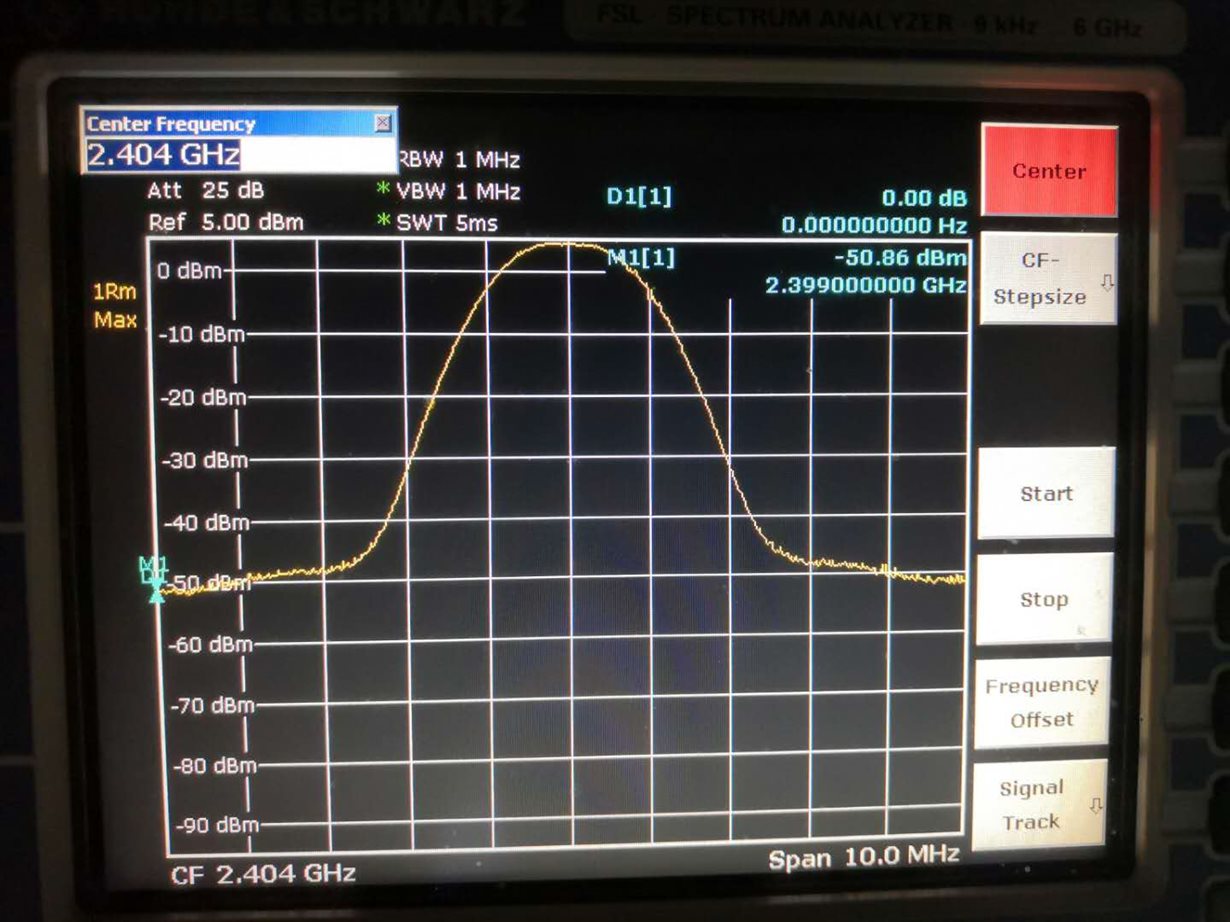
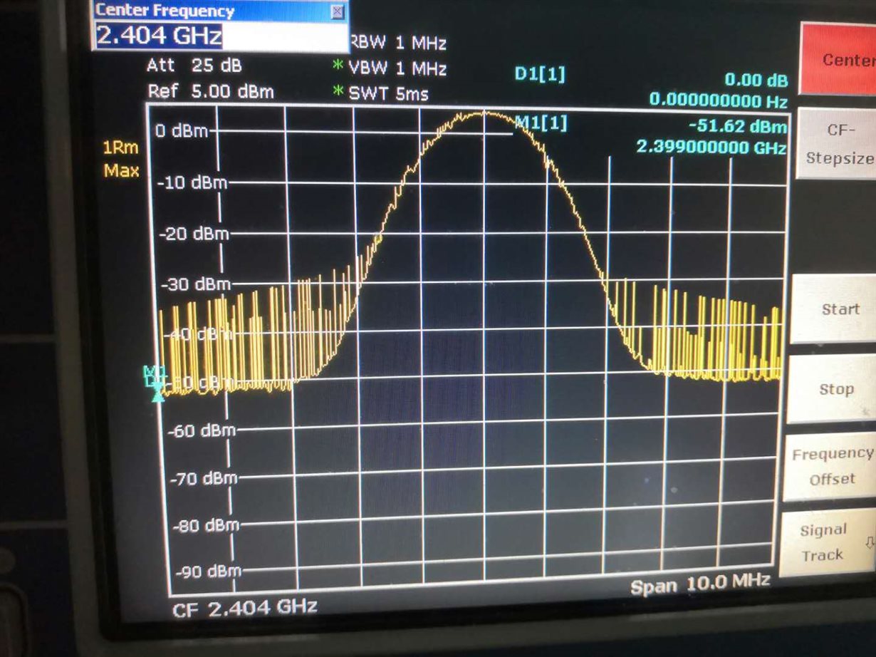
    please refer to this two picture, same configuration with SmartRF Studio but different performance:

    CC1352R (same as CC26X2):

    CC1350(same as CC26X0):

    Thanks!

    LN

  • Hi,

    Thank you for sharing the data.

    We do not have a way to change the PA ramp scheme on BLE PHY on CC1350 or CC2640R2. I am discussing another option with the R&D and will get back to you tomorrow. Can you please confirm that you are using the signal from RF core to enable/disable external PA?

    The post you referred to has information about changing ramp settings for proprietary mode. However, on BLE PHY is supported on CC1350 in 2.4GHz band and we have not tested any proprietary modes on this device and band combination. Also, for 1mbps datarate, you will need BLE PHY, it cannot be done using proprietary mode.

    If you are still interested in <500kbps datarate with proprietary settings and are having trouble implementing PA ramping on it, please share the setting you are using and I will test it out on my setup.

    Regards,

  • Hi,

    we changed the datarate to 250Kbps with proprietary on CC1350 and the CC2650:

    //*********************************************************************************
    // Parameter summary
    // Address0: 0xAA 
    // Address1: 0xBB 
    // Frequency: 2404.00000 MHz
    // Data Format: Serial mode disable 
    // Deviation: 125.000 kHz
    // Packet Length Config: Variable 
    // Max Packet Length: 128 
    // Packet Length: 20 
    // Packet Data: 255 
    // RX Filter BW: 530 kHz
    // Symbol Rate: 250.00000 kBaud
    // Sync Word Length: 32 Bits 
    // TX Power: 5 dBm 
    // Whitening: No whitening 
    #include <ti/devices/DeviceFamily.h>
    #include DeviceFamily_constructPath(driverlib/rf_mailbox.h)
    #include DeviceFamily_constructPath(driverlib/rf_common_cmd.h)
    #include DeviceFamily_constructPath(driverlib/rf_prop_cmd.h)
    #include <ti/drivers/rf/RF.h>
    #include DeviceFamily_constructPath(rf_patches/rf_patch_cpe_prop.h)
    #include DeviceFamily_constructPath(rf_patches/rf_patch_rfe_genfsk.h)
    #include DeviceFamily_constructPath(rf_patches/rf_patch_mce_genfsk.h)
    #include "smartrf_settings.h"
    // TI-RTOS RF Mode Object
    RF_Mode RF_prop =
    {
        .rfMode = RF_MODE_PROPRIETARY_2_4,
        .cpePatchFxn = &rf_patch_cpe_prop,
        .mcePatchFxn = &rf_patch_mce_genfsk,
        .rfePatchFxn = &rf_patch_rfe_genfsk
    };
    // Overrides for CMD_PROP_RADIO_SETUP
    uint32_t pOverrides[] =
    {
        // override_use_patch_prop_genfsk.xml
        // PHY: Use MCE RAM patch, RFE RAM patch
        MCE_RFE_OVERRIDE(1,0,0,1,0,0),
        // override_synth_prop_2440_div2.xml
        // Synth: Set Fref to 4 MHz
        (uint32_t)0x000684A3,
        // Synth: Use 24 MHz XOSC as synth clock, enable extra PLL filtering
        (uint32_t)0x02010403,
        // Synth: Configure faster calibration
        HW32_ARRAY_OVERRIDE(0x4004, 1),
        // Synth: Configure faster calibration
        (uint32_t)0x1C0C0618,
        // Synth: Configure faster calibration
        (uint32_t)0xC00401A1,
        // Synth: Configure faster calibration
        (uint32_t)0x21010101,
        // Synth: Configure faster calibration
        (uint32_t)0xC0040141,
        // Synth: Configure faster calibration
        (uint32_t)0x00214AD3,
        // Synth: Decrease synth programming time-out by 64 us (0x0300 RAT ticks = 192 us)
        (uint32_t)0x03000243,
        // Rx: Set LNA IB offset used for automatic software compensation to 0
        (uint32_t)0x00008883,
        // Rx: Set LNA IB trim value based on the selected defaultPhy.mainMode setting.
        ADI_HALFREG_OVERRIDE(0,4,0xF,0xF),
        // Rx: Set RSSI offset to adjust reported RSSI by -1 dB (default: 0)
        (uint32_t)0x000188A3,
        // override_phy_tx_pa_ramp_gfsk_pa_ramp_12us_agc_reflevel_0x22.xml
        // Tx: Configure PA ramping setting (0x3F). Rx: Set AGC reference level to 0x22.
        HW_REG_OVERRIDE(0x6088,0x3F22),
        // Tx: Configure PA ramping setting
        HW_REG_OVERRIDE(0x608C,0x0413),
        (uint32_t)0xFFFFFFFF
    };
    // CMD_PROP_RADIO_SETUP
    // Proprietary Mode Radio Setup Command
    rfc_CMD_PROP_RADIO_SETUP_t RF_cmdPropRadioSetup =
    {
        .commandNo = 0x3806,
        .status = 0x0000,
        .pNextOp = 0, // INSERT APPLICABLE POINTER: (uint8_t*)&xxx
        .startTime = 0x00000000,
        .startTrigger.triggerType = 0x0,
        .startTrigger.bEnaCmd = 0x0,
        .startTrigger.triggerNo = 0x0,
        .startTrigger.pastTrig = 0x0,
        .condition.rule = 0x1,
        .condition.nSkip = 0x0,
        .modulation.modType = 0x1,
        .modulation.deviation = 0x1F4,
        .symbolRate.preScale = 0x6,
        .symbolRate.rateWord = 0x10000,
        .symbolRate.decimMode = 0x0,
        .rxBw = 0x09,
        .preamConf.nPreamBytes = 0x4,
        .preamConf.preamMode = 0x0,
        .formatConf.nSwBits = 0x20,
        .formatConf.bBitReversal = 0x0,
        .formatConf.bMsbFirst = 0x1,
        .formatConf.fecMode = 0x0,
        .formatConf.whitenMode = 0x0,
        .config.frontEndMode = 0x0,
        .config.biasMode = 0x0,
        .config.analogCfgMode = 0x0,
        .config.bNoFsPowerUp = 0x0,
        .txPower = 0x9330,
        .pRegOverride = pOverrides
    };
    // CMD_FS
    // Frequency Synthesizer Programming Command
    rfc_CMD_FS_t RF_cmdFs =
    {
        .commandNo = 0x0803,
        .status = 0x0000,
        .pNextOp = 0, // INSERT APPLICABLE POINTER: (uint8_t*)&xxx
        .startTime = 0x00000000,
        .startTrigger.triggerType = 0x0,
        .startTrigger.bEnaCmd = 0x0,
        .startTrigger.triggerNo = 0x0,
        .startTrigger.pastTrig = 0x0,
        .condition.rule = 0x1,
        .condition.nSkip = 0x0,
        .frequency = 0x0964,
        .fractFreq = 0x0000,
        .synthConf.bTxMode = 0x0,
        .synthConf.refFreq = 0x0,
        .__dummy0 = 0x00,
        .__dummy1 = 0x00,
        .__dummy2 = 0x00,
        .__dummy3 = 0x0000
    };
    // CMD_PROP_TX
    // Proprietary Mode Transmit Command
    rfc_CMD_PROP_TX_t RF_cmdPropTx =
    {
        .commandNo = 0x3801,
        .status = 0x0000,
        .pNextOp = 0, // INSERT APPLICABLE POINTER: (uint8_t*)&xxx
        .startTime = 0x00000000,
        .startTrigger.triggerType = 0x0,
        .startTrigger.bEnaCmd = 0x0,
        .startTrigger.triggerNo = 0x0,
        .startTrigger.pastTrig = 0x0,
        .condition.rule = 0x1,
        .condition.nSkip = 0x0,
        .pktConf.bFsOff = 0x0,
        .pktConf.bUseCrc = 0x1,
        .pktConf.bVarLen = 0x1,
        .pktLen = 0x14, // SET APPLICATION PAYLOAD LENGTH
        .syncWord = 0x930B51DE,
        .pPkt = 0 // INSERT APPLICABLE POINTER: (uint8_t*)&xxx
    };
    // CMD_PROP_RX
    // Proprietary Mode Receive Command
    rfc_CMD_PROP_RX_t RF_cmdPropRx =
    {
        .commandNo = 0x3802,
        .status = 0x0000,
        .pNextOp = 0, // INSERT APPLICABLE POINTER: (uint8_t*)&xxx
        .startTime = 0x00000000,
        .startTrigger.triggerType = 0x0,
        .startTrigger.bEnaCmd = 0x0,
        .startTrigger.triggerNo = 0x0,
        .startTrigger.pastTrig = 0x0,
        .condition.rule = 0x1,
        .condition.nSkip = 0x0,
        .pktConf.bFsOff = 0x0,
        .pktConf.bRepeatOk = 0x0,
        .pktConf.bRepeatNok = 0x0,
        .pktConf.bUseCrc = 0x1,
        .pktConf.bVarLen = 0x1,
        .pktConf.bChkAddress = 0x0,
        .pktConf.endType = 0x0,
        .pktConf.filterOp = 0x0,
        .rxConf.bAutoFlushIgnored = 0x0,
        .rxConf.bAutoFlushCrcErr = 0x0,
        .rxConf.bIncludeHdr = 0x1,
        .rxConf.bIncludeCrc = 0x0,
        .rxConf.bAppendRssi = 0x0,
        .rxConf.bAppendTimestamp = 0x0,
        .rxConf.bAppendStatus = 0x1,
        .syncWord = 0x930B51DE,
        .maxPktLen = 0x80, // MAKE SURE DATA ENTRY IS LARGE ENOUGH
        .address0 = 0xAA,
        .address1 = 0xBB,
        .endTrigger.triggerType = 0x1,
        .endTrigger.bEnaCmd = 0x0,
        .endTrigger.triggerNo = 0x0,
        .endTrigger.pastTrig = 0x0,
        .endTime = 0x00000000,
        .pQueue = 0, // INSERT APPLICABLE POINTER: (dataQueue_t*)&xxx
        .pOutput = 0 // INSERT APPLICABLE POINTER: (uint8_t*)&xxx
    };
    we get this(both CC1350 and CC2650,please set your spectrum analyzer :detector positive peak):
    but with the cc1352 and cc2652,we get this:

    this is what we want !!!


    help, please!

    Thanks!

    LN

  • Hi,

    As mentioned before, we have not tested proprietary modes in 2.4GHz band on CC1350. However, I would recommend using the settings closest to the datarate you are interested, in this case, 200kbps for sub-GHz band for AGC and PA ramping. Copying the settings below for convenience. You could also experiment with these settings as per the other post to increase ramping time without losing preamble symbols.

    // Tx: Configure PA ramping setting (0x10) for approximately 5 us PA ramp time. Rx: Set AGC reference level to 0x1C.

    HW_REG_OVERRIDE(0x6088,0x101C),

    // Tx: Configure PA ramping setting (0x08) for approximately 5 us PA ramp time

    HW_REG_OVERRIDE(0x608C,0x0813),

    Another option is to use the TX_START signal instead of PA_ENABLE signal to enable external PA. The source of noise is CC1350 and with this change, the timing for external PA enable might filter some noise from CC1350 to output of PA.

    On CC265x, I have to try out settings in the lab to make further suggestions.

    What is the customer requirement here, are they open to using either device and what is the minimum datarate requirement?

    Regards,

  • Hi,

    Have you test your code  on CC1350 or CC2650?it is easy to test with the LaunchPad CC1350/CC2650. 

    i change the ramping time and set the TX_START signal instead of PA_ENABLE signal to enable external PA as your suggestion, it does not work even change the time to 100us.(both CC1350 and CC2650)

    The  datarate of  requirement is changeable from 100Kbps to 250Kbps.

    We want to konw if  possible to get a signal like the CC1352/CC2652 we have post ? we have lost much time,could TI  give us a conclusion?


    Thanks!

    LN

  • Hi,

    The results on CC2650 or CC1350 will not be the same as CC1352 since the ramping schemes are different on these platforms. I am testing different options in our lab to provide recommendations on the best settings at 250kbps on CC26xx device. Since it involves lab testing, it will take us couple of days to provide data and I will post an update on Wednesday.

    Thank you for your patience.

    Regards,

  • Hi SVS

    Is there a result of the problem? Customers who are not addressing the issue in the near future will face huge indemnities. I hope you can support it.

  • Hi,

    Is there any new progress about this problem?

    Thanks!

    LN

  • Hi,

    I am closing this thread because this is being addressed by the TI field team.

    Regards,