Other Parts Discussed in Thread: MSP430G2553, , MSP430F5438
Tool/software: Code Composer Studio
Hello
I am trying to program the CC1200 with MSP430G2553 LaunchPad. The setup is supposed to transmit data every 5 seconds. I wired the CC1200 EM as described below:
P1.1 is connected to the MISO pin on the CC1200EM.
P1.2 is connected to the MOSI pin on the CC1200EM.
P1.4 is connected to the SCLK pin on the CC1200EM.
P1.5 is connected to the CSN pin on the CC1200EM.
VCC is connected to the Vdd pin on the CC1200EM.
GND is connected to the GND pin on the CC1200EM.
Other pins are unconnected. (GPIOs).
You can see the configuration as shown below.
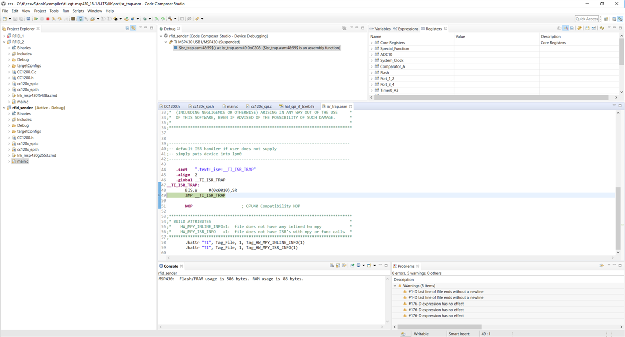
I have written a code in Code Composer Studio and included the header files: cc120x_spi.h cc120x_spi.hin the code examples from ti webpage / and CC1200.h that I exported from SmartRF Studio 7, CC1200.h. In the timer interrupt vector, I want to send one byte for example. The compiler builds the project without any error, but when I run it, it stuck there. When I pause it, the following page shows up . My code is below:
#include <msp430.h>
#include <cc120x_spi.h>
#include <CC1200.h>
/**
* main.c
*/
uint8 txBuffer[4]={"helo"};
int count=0;
int main(void)
{
WDTCTL = WDTPW | WDTHOLD; // stop watchdog timer
P1OUT = 0x00; // P1 setup for LED & reset output
P1DIR |= BIT0 + BIT5; //
P1SEL = BIT1 + BIT2 + BIT4;
P1SEL2 = BIT1 + BIT2 + BIT4;
UCA0CTL0 |= UCCKPL + UCMSB + UCMST + UCSYNC; // 3-pin, 8-bit SPI master
UCA0CTL1 |= UCSSEL_2; // SMCLK
UCA0BR0 |= 0x02; // /2
UCA0BR1 = 0; //
UCA0MCTL = 0; // No modulation
UCA0CTL1 &= ~UCSWRST; // **Initialize USCI state machine**
IE2 |= UCA0RXIE; // Enable USCI0 RX interrupt
TA1CCTL0 = CCIE; // CCR0 interrupt enabled
// TA1CCR0 = 1250000;
TA1CTL = 0x00C0 + TASSEL_2 + MC_2 + TACLR; // ID=8 | ACLK | contmode| clear TAR |
__bis_SR_register(LPM0_bits + GIE); // Enter LPM0 w/ interrupt
}
// Timer A0 interrupt service routine
#if defined(__TI_COMPILER_VERSION__) || defined(__IAR_SYSTEMS_ICC__)
#pragma vector=TIMER1_A0_VECTOR
__interrupt void TIMER1_A0_ISR(void)
#elif defined(__GNUC__)
void __attribute__ ((interrupt(TIMER1_A0_VECTOR))) TIMER1_A0_ISR (void)
#else
#error Compiler not supported!
#endif
{ if (count==10)
{
P1OUT &= ~BIT5; // Now with SPI signals initialized,
P1OUT|= BIT0;
CC120X_SRES;
//while (!(IFG2 & UCA0TXIFG)); // USCI_A0 TX buffer ready?
UCA0TXBUF = txBuffer[0];
CC120X_SINGLE_TXFIFO;
CC120X_STX;
count=0;
}
else
{
count++;
P1OUT &= ~BIT0;
P1OUT |= BIT5; // Now with SPI signals initialized,
}
}
Can anyone guide me if I declared the transmission protocol in the timer interrupt correctly and why I am getting stuck in the trap (shown in the above picture)?
Your help is most appreciated!
Saber


