This thread has been locked.

If you have a related question, please click the "Ask a related question" button in the top right corner. The newly created question will be automatically linked to this question.

CC1352P: CC1352P Rev E resetting with CLK_LOSS or hanging on EasyLink_Params_init()

Part Number: CC1352P
Other Parts Discussed in Thread: CC1350

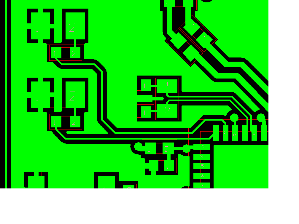
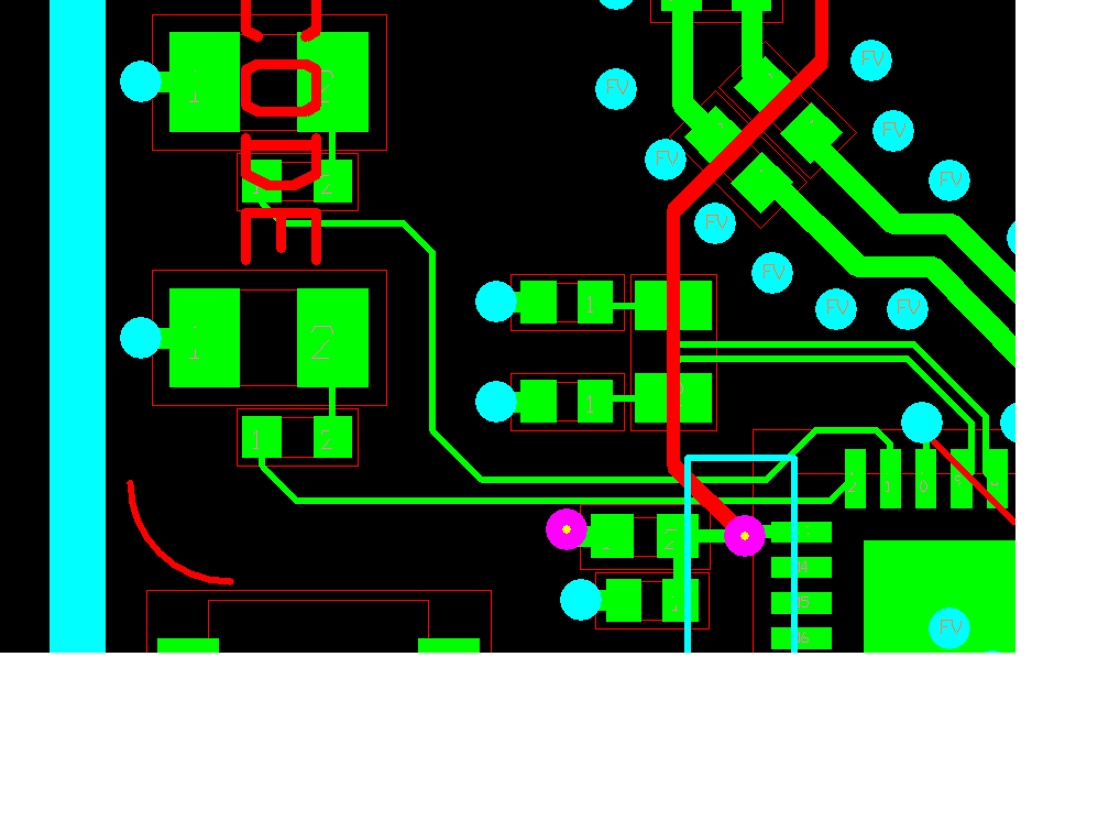
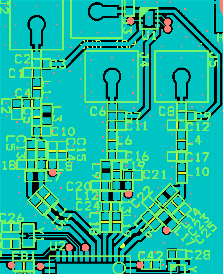
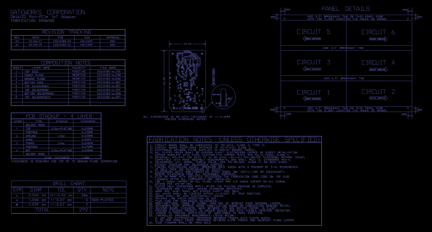
Our board design is based off the CC1352P1_LAUNCHXL, the obvious changes from the launchpad include:

 - we remove the TIVA chip and add a JTAG connector (we program it with our own JTAG dongle)

 - we use an Abracon ABM12W-48.0000MHZ-7-D1X-T3 crystal (48MHz, 7pF load capacitance, -40 to +85C temp, +/-10ppm Freq tolerance, +/-20ppm Freq stability)

I'm using CC1352P revE chips and simplelink_cc13x2_26x2_sdk_3_20_00_68 with examples/rtos/CC1352P_4_LAUNCHXL/easylink/rfEasyLinkNp.

I've got 20 prototype boards and so far it appears that every one of the eventually experiences one of two different issues using unmodified rfEasyLinkNp application:

- AT+I 1 EasyLink_Params_init(50kbps2gfsk) will hang

- AT+TX <msg> (EasyLink_transmit()) will cause a chip level reset where SysCtrlResetSourceGet indicates CLK_LOSS as the reason

When a board gets into one of the above cases (which it seems to do sometimes after 10000+ successful TX/RX packets) it seems to stick in this case for quite some time even after power cycles (as in power cycle the board and it will hang on the first AT+I or reset on the first AT+TX like a latch-up condition).

I expect an issue with the 48MHz crystal so have started exploring different capacitor values (we use 8pf caps in the tank and I've been told that the CC1352P1_LAUNCHXL uses 7.5pf) including removing the caps and using the internal array... nothing has made a markable difference.

I would like to understand how to determine which clock triggered the CLK_LOSS in case its not the 48MHz. I'm reading the following registers after the chip comes out of reset and after I've initialized the UART:

STAT0:0x00000006
STAT1:0x0000001a
RESETCTL:0x00003bea

The reference manual states that in order to trigger a reset on CLK_LOSS you need to set both DDI_0_OSC:CTL0.CLK_LOSS_EN and AON_PMCTL:RESETCTL.CLK_LOSS_EN which is not enabled after boot. I don't enable these yet I find they are both enabled (why?). I have tried to disable them with the following code added in rfEasyLinkNp.c:atnpFxn() but the reset still occurs (why?).

uint32_t reg = HWREG( AON_PMCTL_BASE + AON_PMCTL_O_RESETCTL );
uart_printf("RESETCTL:0x%08lx\r\n", reg); // shows 0x00003bea
reg &= ~AON_PMCTL_RESETCTL_VDDS_LOSS_EN;
HWREG(AON_PMCTL_BASE + AON_PMCTL_O_RESETCTL) = reg;
uart_printf("RESETCTL:0x%08lx\r\n", HWREG(AON_PMCTL_BASE + AON_PMCTL_O_RESETCTL)); // shows 0x00003aea

HWREG(AUX_DDI0_OSC_BASE + DDI_O_CLR + DDI_0_OSC_O_CTL0 ) = DDI_0_OSC_CTL0_CLK_LOSS_EN;
printf("DDI_0_OSC_CTL0:0x%08lx\r\n", HWREG(AON_PMCTL_BASE + AON_PMCTL_O_RESETCTL)); // shows 0x00003aea

Please advise. This issue has been plaguing me for weeks and I'm unable to ship product because of this instability. Please do NOT close this thread if you don't hear from me in a day... that does NOT mean the issue is resolved, it just means I haven't been able to get back to it.

  • I think this is related to a fault caused by the XOSC_LF (the 32khz external crystal) as I've taken boards that exhibit this issue and set SET_CCFG_MODE_CONF_SCLK_LF_OPTION=0x0 to derive the LF clock from the HF OSC and the issue goes away. I'm still unclear why its so difficult to re-create this issue in the first place but once you encounter it it seems to 'latch-up' on the board and not go away.

    We use an Abracom ABS05-32.768KHZ which is 32.768KHz, +/-20ppm Freq tolerance, 12pf load capacitance crystal with 12pf tank caps and I notice the CC1352P ref manual states the load capacitance must be between 6pf an 12pf. It is not stated what the CC1352P1_LAUNCHXL uses for a 32khz crystal but the tank caps are 12pf and 15pf (which seem wrong as they are unbalanced).

    Do you think its the load capacitance of our external XOSC_LF that is the issue or could it be more related to Advisory Radio_02 which is about CLK_LOSS from the 32KHz crystal due to RF impedance mismatch?

    Tim

  • 12 pF/ 15 pF is a fairly normal way to get a load cap in between two E12/24 cap values since Cload = C1 // C2. If you look at the BOM list for the LP, we use a Epson FC-135 32.7680KA-AG0 which is a Cload = 7 pF. If you use a xtal that requires Cload = 12 pF, please confirm that you use load caps that gives C1//C2 ~ 11 pF (some parasitic cap due to PCB routing has to be factored in) 

    Please confirm that the following override is in your override list: 

    HW_REG_OVERRIDE(0x60A8,0x0401),

    This should be in place when you use the latest SDK/ export settings with version 2.15 of Studio.

    It's not clear which output power you are using. Do you see a change is you go below 17 dBm as the Advisory Radio_02 indicate? 

    It could be also interesting to look at your layout of the 20 dBm PA routing from the pins towards the antenna. 

  • Yes HW_REG_OVERRIDE(0x60A8,0x0401) is in there for Mode 1 of simplelink_cc13x2_26x2_sdk_3_20_00_68/examples/rtos/CC1352P1_LAUNCHXL/easylink/rfEasyLinkNp. I see this issue at 20dBm as well as 14dBm.

    Because I've noticed that boards having this issue seem to be rectified if we #define SET_CCFG_MODE_CONF_SCLK_LF_OPTION 0x0 (using the 48Khz as a source for SCLK_LF instead of the ext 32kHz) I started scoping the 32.768KHz XTAL. I find that on some boards this crystal doesn't even come up and those boards do not trigger CLK_LOSS (no clock to even be lost perhaps?), other boards there is a definite 'glitch' in the 32kHz when a packet is transmitted (which is what is causing CLK_LOSS to be triggered), and other boards have a completely stable 32kHz with no glitches during transmit. I verified the same using 14dBm tx as well as 20dBm and in fact the boards that have a glitching 32kHz get worse at 14dBm.

    This makes me believe we have a 32kHz crystal start-up issue. I've modified boards to have a 7pF XTAL with 9.5pF tank caps (instead of the 12.5pF) to see if the crystal came up and on some boards this made a difference but others still have the problem. This sure seems like the Radio_02 errata but its occurring regardless of the High Gain PA being used and at room temperature.

    What are the reprecusions of using '#define SET_CCFG_MODE_CONF_SCLK_LF_OPTION 0x0' as a workaround? I understand that Standby mode won't work, but its not clear to me if there will be other issues such as RTC drift?

  • Hi Tim,

    It definitely sounds like something is suspicious with your 32k crystal, and not being specifically related to the errata issue. 

    With SCLK_LF_OPTION set to 0, the device will be prevented from entering Standby, as you say, otherwise there are no downsides. The RTC tolerance will be the same as your 48 MHz XOSC tolerance. Alternatively, you can use SCLK_LF_OPTION 3 which will derive the RTC from the 32k RCOSC. That will allow the system to enter Standby, but the RTC will be highly inaccurate. 

    Can you share a snippet of your layout showing the 32 kHz crystal and its connections to the IC?

    Regards,
    Fredrik

  • Fredrik,

    I've noticed that down in the SDK source/ti/drivers/power/PowerCC26X2.c:Power_init() function there is code that sets up a timer to check XOSC_LF activation and if XOSC_LF isn't running (not clear exactly how this is checked) it does not enable CTL0.CLK_LOSS_EN such that a board without a 32kHz osc won't end up triggering a reset with CLK_LOSS. This explains why I never saw any failures on boards where the 32kHz stopped coming up completely. What is puzzling me is that on a board in this condition where the 32kHz osc is not functioning for whatever reason I find that Clock_getTicks()) and HWREG(AON_RTC_BASE + AON_RTC_O_SEC) do show the RTC ticking. The RM seems to indicate the only source for RTC is XOSC_LF so I'm not clear what the effect is of no XOSC_LF.

    I'm also very puzzled over why it seems to take minutes to hours of transmitting packets (or perhaps just running) before some boards get into a state where the 32kHz OSC stops functioning properly. When this latch up issue occurs If the boards sit for a while (perhaps a day or so) the OSC appears to start working again. Are we stressing or damaging the OSC somehow?

    Here is a snippet of the top layer showing pin 8 and 9 routing to the 32kHz xtal (which is in the center).

    Here is a snippet of all layers... the only thing running across the 32kHz is VDD to pin 13 and DIO10. There is a filled power layer and a ground layer in the middle.

    Tim

  • Hi Tim,

    The clock-loss detector compares SCLK-LF against SCLK-HF, so it should be able to run regardless of SCLK-LF source. Of course, if XOSC-LF never starts, it will never trigger the clock loss detector as the clock is never lost (the device will not switch to XOSC-LF if it does not run). 

    If XOSC-LF is selected as SCLK-LF source, but the crystal oscillator fails to start the device will default to deriving SCLK-LF from RCOSC-HF, the 48 MHz RC oscillator. This is why you see the RTC ticks still going.

    The layout for the 32 kHz crystal and its load caps looks ok, no problems there. What I can see of the RF matching for the PA output though is not good. Could you show me the full RF matching layout?

    Regards,
    Fredrik

  • Fredrik,

    Here is a larger view of the top layer showing the RF paths.

    Tim

  • Hi Tim,

    The long differential trace for the PA output is not good, and will most likely cause issues. You must follow the reference designs accurately for component placement. 

    I am a bit baffled by your statement about observing clock-loss also with the 14 dBm output, is that really correct? 

    What PCB stack-up are you using?

    Regards,
    Fredrik 

  • Fredrik,

    Fredrik K said:

    The long differential trace for the PA output is not good, and will most likely cause issues. You must follow the reference designs accurately for component placement. 

    We are using 402's not 201's so we are as about as tight as we can get. The layout is the same as the launchpad with the exception of the 402's vs the 201's.

    Fredrik K said:

    I am a bit baffled by your statement about observing clock-loss also with the 14 dBm output, is that really correct? 

    Correct - once a board gets into this 'mode' I can see large glitches via a scope on the 32kHz occur when a packet is transmitted which is what causes CLK_LOSS. When in this mode I'll see it occur even at very low TX powers such as 8dBM. It does not take high gain PA to even get it into this mode.

    Fredrik K said:

    What PCB stack-up are you using?

    stackup:

    1: TOP 0.5oz+plating, 0.035mm thick
    PREPREG 0.175mm thick
    2: GND 1.0oz 0.035mm thick
    CORE 0.51mm thick
    3: PWR 1.0oz 0.035mm thick
    PREPREG 0.175mm thick
    4: BOT 0.5oz+plating 0.035mm thick
    total thickness 1.0mm

    I believe I can get a board into this mode manually by unconnecting and reconnecting the antenna at J3 or by even touching repeatedly the GND of the unconnected J5 2.4GHz antenna with an untermitated probe (the code currently is only transmitting sub1ghz so there is no antenna connected to 2.4GHz). The board will remain in this mode (resetting with CLK_LOSS while transmitting 8dBm sub1ghz) for perhaps minutes or hours and then eventually may get stable again. Some boards get into this mode on their own just by running overnight in the lab looping over transmitting sub1ghz packets at 8dBm.

    The code I'm running is examples/rtos/CC1312R1_LAUNCHXL/easylink/rfEasyLinkNp/rfEasyLinkNp.c with the following in place of the looping call to AtProcess_processingLoop():

    #define usleep(x) Task_sleep(x / Clock_tickPeriod)
    
    usleep(1000000);
    doAT("+I 1"); usleep(500000);
    doAT("PPW?"); usleep(500000);
    doAT("PPW=8"); usleep(500000);
    doAT("PPW?"); usleep(500000);
    
    uint32_t tx = 0;
    while (1) {
      uprintf("%lu", tx++);
      uprintf(" sec:%d", HWREG(AON_RTC_BASE + AON_RTC_O_SEC));
      uprintf(" STAT0:0x%x", HWREG(PRCM_BASE + PRCM_O_PDSTAT0));
      uprintf(" STAT1:0x%x", HWREG(PRCM_BASE + PRCM_O_PDSTAT1));
      uprintf(" CTL0:0x%lx", HWREG(AUX_DDI0_OSC_BASE + DDI_0_OSC_O_CTL0));
      uprintf("\r\n");
      doAT("+TX foo"); usleep(100000);
    }

    The boards are currently built with the RF switch connected to the sub1ghz and high-pa sub1ghz where the 2.4ghz is isolated so on that layer image C3/C7/U1/J3/C8/J5 are loaded and C2/C6/C9/J2/J4 are unloaded.

    Can you explain to me what the effect of transmitting sub1ghz without an antenna (no termination) on a) the 2.4Ghz J2 (noting we are using EasyLinkNp phyMode 1 (sub1ghz) and on b) the combined sub1ghz J3 that's currently being used? I'm wondering if the connection at J3 mechanically is unsound causing an occasional massive impedence unbalance which is damaging (permanently or temporarily) the crystal or something else?

    I've even had 2 boards out of 10 being tested overnight (ESD, lab conditions) completely die where I can no longer identify the chip on the JTAG chain. Something seems very wrong with this chip that we did not encounter in a previous design that used  the CC1350. I have two rev-E silicon launchpads over here, perhaps I'll start running them over the same tests.

    Tim

  • Tim Harvey9 said:

    The code I'm running is examples/rtos/CC1312R1_LAUNCHXL/easylink/rfEasyLinkNp/rfEasyLinkNp.c with the following in place of the looping call to AtProcess_processingLoop():

    Sorry, code based off of examples/rtos/CC1352P1_LAUNCHXL/easylink/rfEasyLinkNp/rfEasyLinkNp.c

  • From what I have seen so far I can't see why the 32 kHz xtal should be behaving like what you are seeing.

    I would like to do a full schematic/ layout review in case it's something in the layout/ schematic that are not visible on what you have shown so far. You can send the files to me in a private message if you don't want to post the design openly on the forum. (Send me a friend request to be able to send me a message, I need schematic as pdf and layout as gerber)

  • Thanks for looking into this. I've messaged you the schematic and gerbers.

    Tim

  • I could not see anything that could explain what you are seeing. 

    Two long shot tests:

    - Does the same happen if you turn off the DCDC (only using the LDO)?

    - Have you tried to swap the 32 kHz xtal you are using between your board and a LP and see if the issue follows the xtal? Remember to also change the load caps. 

  • TER said:

    I could not see anything that could explain what you are seeing. 

    Two long shot tests:

    - Does the same happen if you turn off the DCDC (only using the LDO)?

    - Have you tried to swap the 32 kHz xtal you are using between your board and a LP and see if the issue follows the xtal? Remember to also change the load caps. 

    I will try these things.

    What would happen if the external antenna connection is not robust enough? Does any damage to the chip/xtal occur if you transmit without an antenna? It seems like removing the antenna puts it into this mode where even after re-attaching the antenna the crystal can be negatively affected for some time.

    Tim

  • As far as I know we haven't seen any bad effects of not terminating the antenna. A PA may get unstable without load but that is typically on low temperatures. Would the typical use case be one or more unterminated RF path or will they normally go to the switch? It would be interesting to see if you manage to get a launchpad in this state or if this is just linked to your implementation of the hardware. It would make it easier to debug if it's possible to recreate on more noards than just yours. 

  • I have not been able to get a launchpad in this state... I've had 2 of them running a tx loop for several days now with no issues.

  • What is the current status of your testing? 

  • I have narrowed down 2 boards out of 15 that fairly easily exhibit CLK_LOSS (from the 32kHz glitches) at 8dBm tx. I've verified that using the LDO on these (by removing the ferrite and setting CCFG appropriately) doesn't make a difference. I have never seen an issue on the 2 launchpads I have but I'm not convinced I would with such a small number I have to test.

    I do know that when transmitting at 20dBm on all of the boards I have if I remove the antenna I easily get glitches on the 32kHz and an eventual CLK_LOSS which again sounds exactly like the errata but it happens at room temp, so I feel like whatever is wrong that causes that errata is a bigger issue than TI thinks. I'm not clear what the expected behavior is when you have no antenna and try to transmit via the high gain PA.

    Because this has been so problematic my thought is to remove the 32kHz crystal from our boards (understanding that we loose standby mode) and move on.

    Tim

  • We have determined that we failed to specify trace impedance to our board house which is very likely leading to an impedance mismatch that is causing this issue. It seems to cause the same issue that the Radio 2 advisory discusses just at room temp and without necessarily using the high gain PA so I still believe that advisory is too conservative.

    The SWRA640C CC13xx/CC26xx Hardware Configuration and PCB Design Considerations document recommends a board stackup that can't work for us in the various designs we wish to incorporate the CC1352P. What are the impedance that should be met at various nets in the Launchpad?

    Tim

  • I may have forgotten to check the stack-up when I review your layout. Was the stack-up information included and in which file? 

  • The stack-up we use is detailed in the 'FAB' file within the gerber zip file I sent.

  • Could you "translate" the .FAB file for me? 

    It's not easy for me to see which part of that file that describe the stack-up.

  • I woke up at 2 AM today to realize that my last post should have been erased... 

    But as far as I see this is the stack-up we recommend, it's the distance from layer1 to layer2 that is the important parameter here. 

  • We did RF Power testing on our board using rfCarrierWave and found that we are seeing less than 10dBm when configured for 20dBm. We found that we omitted C483 from the reference design on our board (this is an AC coupling cap on the output of the SKY13317-373 RF switch). Adding a cap there brings the RF power up to 19.7dBm. We did not realize that a DC bias was being applied within the SKY13317 but apparently it is (the SKY13317 datasheet clearly says you need caps on the input and outputs). The part has no Vin so it can only be getting power from the V1/V2/V3 pins... strange.

    So the fact that our trace spacing following the balun is a bit inadequate is likely not a factor here (or extremely minimal) and the missing cap seems to be the culprit.

    I'm having some boards modified to insert the cap and will test them to make sure we no longer see any CLK_LOSS.

  • I will be closing this thread since the issue seems to be solved. Please feel free to re-open it if you have additional comments/feedback. Also, please re-open it if you want TER tom comment on your findings. He is OoO until the 25th, but I can have him look at it when he gets back if you want to.

    BR

    Siri