This thread has been locked.

If you have a related question, please click the "Ask a related question" button in the top right corner. The newly created question will be automatically linked to this question.

Planar monopole 868 MHz antenna design - modify TI antenna designs

Hello everyone,

I am trying to design planar antenna 868 MHz, I am limited by shape/dimensions of existing PCB, so I was thinking about modifying existing antennas from TI (DN023, DN024, DN031), see below.

I tried, I failed.... it was impossible to achieve similar results as it was state in design note. So I decided to simulate basic monopole antenna, which should be easy and than to modify it. I need antenna for 868 MHz so by basic math quarter-wave in free space is approx. 86 mm long, in PCB it should be around 65 mm. 

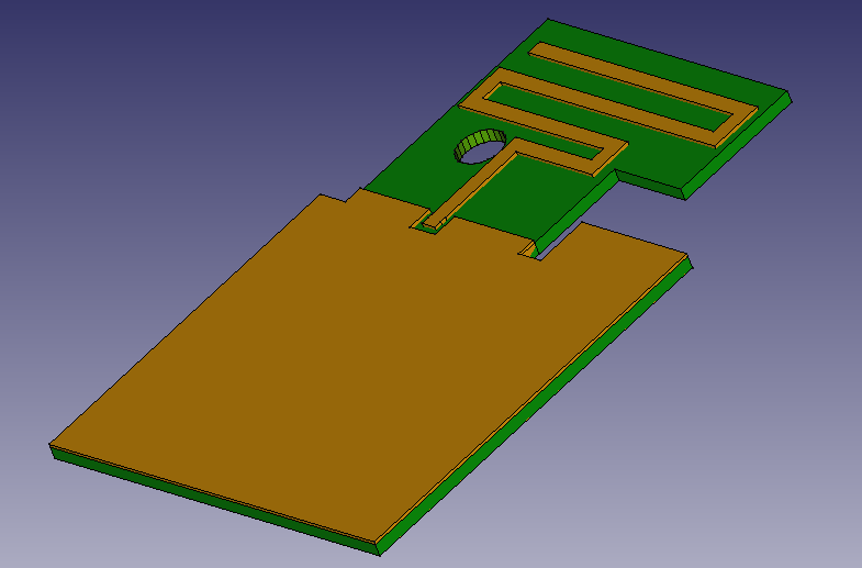
I create model to simulate (see below) with ground big enough 85 mm what is quarter-wave in free space and monopole from 50 to 85 mm, width 2 mm, ground bottom and monoople top are perfect E, lumped port 50 ohm, at FR4 1.6 mm, airbox is 345 mm big (full wave in free space) X,Y,Z and antenna is in the center of it. It should work (not perfect) without matching circuit, I want to add it in next step.

After simulation I get s11 parameters like these.

What am I missing or doing wrong? Could any of you guys help me with that? Thank you very much in advance for your answers.

  • Hi,

    For your board design, I would base the antenna design on DN024 since this should (virtually) fit if you flip the antenna structure vertically. This antenna we use on LPs and is ideal for 868-915 MHz. The exact length of the antenna will be dependent on the GND plane size. The length of this antenna is usually much longer than a quarter-wave since there are opposing currents in the meandering which effectively shortens the antenna.

    Always good practice to add a pi-filter for antenna matching purposes as well.

    Regards,

       Richard 

  • Hi Richard,

    thank you very much for your help. I have already made design according your suggestion and it seems (simulations) good.

    Do you think that there is there any chance to have NFC antenna on the other side of board and both of antennas will work? Do you have any suggestion how to implement both of this antenna on the same board?

    Thank you very much for answer.

  • Hi,

    Good to here that the simulations are looking better.

    I would place the NFC antenna within the GND plane, or at the bottom of the board, then this will not affect the sub-1 antenna too much.

    Regards,

       Richard