This thread has been locked.

If you have a related question, please click the "Ask a related question" button in the top right corner. The newly created question will be automatically linked to this question.

CC1352P: CC1352P1 RF power table or adjustment way

Part Number: CC1352P

Hi TI,

As to CC1352P1, we would like to know below things during the design,

1. Is there transmit power table accessible by FW to do the modification? (e,g High power port to set TX power 17dBm)

2. There is a proximity sensor to detect the antenna to the body so the SAR testing will mandate the TX power to a upper limit that might be lower than 20 dBm, in that case we are wondering whether >98% duty cycle Packet TX is allowed for this modification purpose (via test firmware or which register)?

Thanks~

Wilson

  • 1) Have you looked at the power table provided in SmartRF Studio? 

    2) Not sure if I understand what you mean here. It sounds like you can detect when you are too close to a human body and want to reduce the output power in this case . But it's not clear why you are mentioning packet tx?

  • Hi TI,

    Answers:

    1. We do not know where to look power table, can you guide us (via Smart RF studio or others) ?

    2. Yes and we will use CW TX. 

    In our system design we have the sensor (antenna power) output to the DIO_27 pin or the other way sensor output to the dedicated system MCU then going into the UART0 pin

    Thanks

  • Hi, 

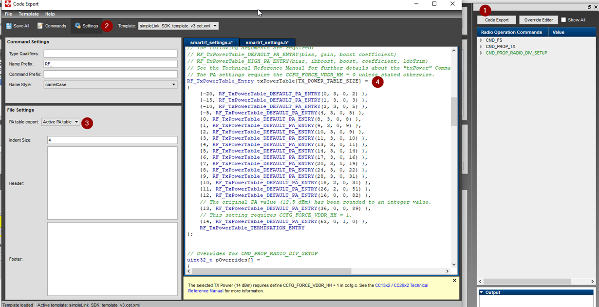
    1. You'll find the PA table here:

    1. Inside the Device Control Panel click "Code Export"

    2. Open the settings panel and make sure 

    3. PA table export "Active PA table" is selected in the drop down menu. 

    4. The PA table is den available in the smartrf_settings.c-file.

    -Simon

  • Hi Simon,

    Thanks for suggestion.

    Our device configuration:

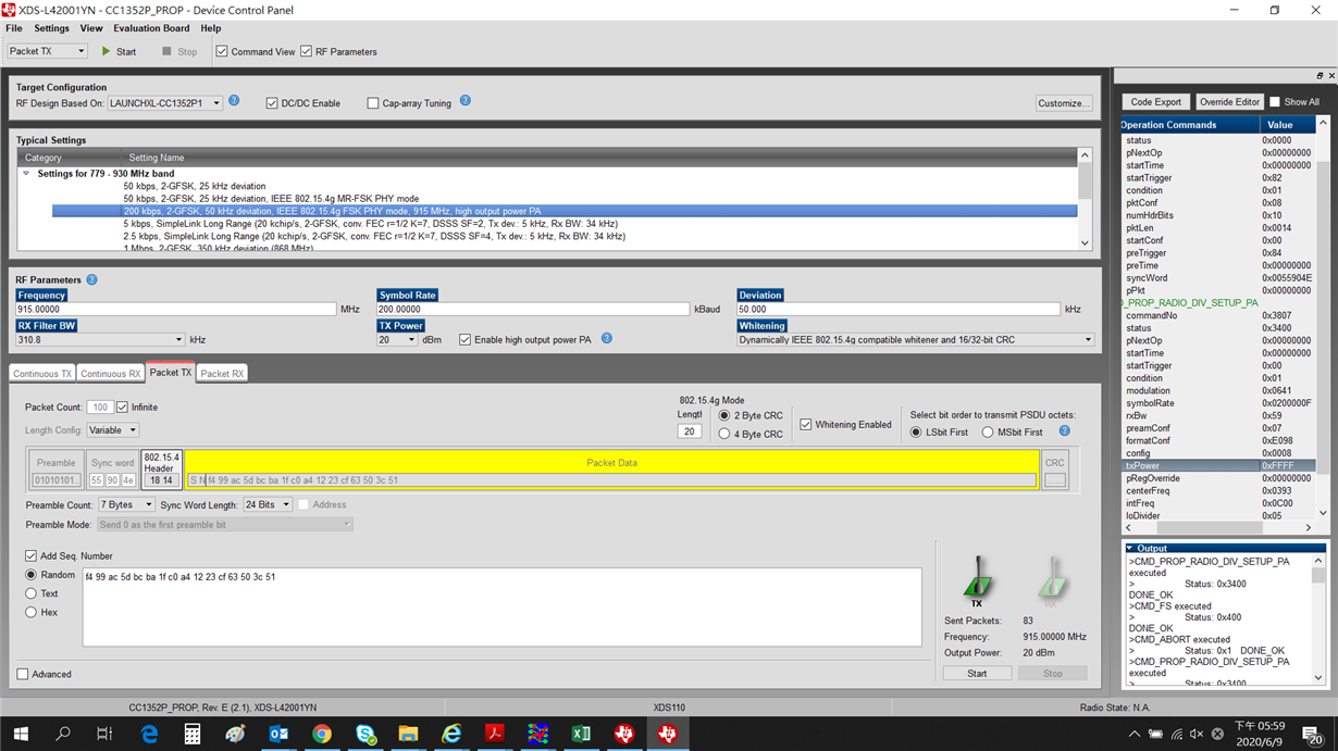
    200 KHz 2-GFSK,...high output PA; 'enable high power PA' is selected

    When entering device control panel, looking into CMD_PROP_RADIO_DIV_SETUP_PA, we see the value output always hold on the value of 0xFFFF, but the measured power really changes to what we set (the value below 20 dBm)  at 'TX power'. However, if we use normal PA port  (do not select 'enable high power PA') then the value output to other value than 0xFFFF  

    1. Is it the bug of smartRF tool? 

    or is there different PA table in our device firmware since we see that different table selections beside 'active PA table', for example standard and high power PA tables  (combined)

    2. The second question is I see EasyLink API via AT command interface can change the TX power but we didn't try it yet as we do not know if UART0 pin can send AT command for CW or PER TX

    3. In ccfg default setting, TX power is 12dBm, so if we going to make it higher, where can we find the setting of CCFG_FORCE_VDDR_HH set to 1?

    Thanks, Wilson Chen

  • Due to two different PAs we have two different PA tables. When .txPower = 0xFFFF the HPA is used. If you select to use the 20 dBm PA  by ticking the "enable High Power PA" and do a code export you will see entries 

    RF_TxPowerTable_Entry txPowerTable[TX_POWER_TABLE_SIZE] =
    {
        {14, RF_TxPowerTable_HIGH_PA_ENTRY(13, 0, 0, 28, 0) },
        {15, RF_TxPowerTable_HIGH_PA_ENTRY(18, 0, 0, 36, 0) },
        {16, RF_TxPowerTable_HIGH_PA_ENTRY(24, 0, 0, 43, 0) },
        {17, RF_TxPowerTable_HIGH_PA_ENTRY(28, 0, 0, 51, 2) },
        {18, RF_TxPowerTable_HIGH_PA_ENTRY(34, 0, 0, 64, 4) },
        {19, RF_TxPowerTable_HIGH_PA_ENTRY(15, 3, 0, 36, 4) },
        {20, RF_TxPowerTable_HIGH_PA_ENTRY(18, 3, 0, 71, 27) },
        RF_TxPowerTable_TERMINATION_ENTRY
    };

    named _HIGH_PA_ENTRY. You will also find a entry named pOverridesTx20 which contains TX20_POWER_OVERRIDE(0x001B8ED2), which sets the output power of the HPA in this case. 

    2) I have to check. What are you going to use the AT commands for? 

    3) This is done in syscfg:

  • Hi, Simon,

    1. I will try later.

    But where can we check the physical definition of each element (18 stands for? 3 stands for?) of the power row (18, 3, 0, 71, 27)

    2. I am just thinking a way that body sensor output can trigger the action enable PA table to lower the power in order to pass FCC SAR, and the method via DIO_27 or UART0 per my first mail to TER on 6/8. however I still get no answer though it is more SW kind of problem. So, AT command is just my thought might be an option to walk through

    3. syscfg in not handled by CCS system configuration tool? In our device

    Thanks,

    Wilson Chen

  • 1) See https://dev.ti.com/tirex/content/simplelink_cc13x2_26x2_sdk_4_10_00_78/docs/proprietary-rf/proprietary-rf-users-guide/proprietary-rf/tx-power.html

    2) Do you have a link to the E2E post you refer to? 

    3) Not sure what you mean here, if you import an example from the newest SDK for CC1352P you will get a syscfg file. See https://dev.ti.com/tirex/content/simplelink_cc13x2_26x2_sdk_4_10_00_78/docs/proprietary-rf/proprietary-rf-users-guide/proprietary-rf/tx-power.html if you don't use syscfg

  • Hi TI,

    For item 2, as this post discussed with TER earlier, we were saying to our schematic design via Sensor output to DIO_27 pin or MCU to UART0 pin, whether it can reduce the power when the antenna is too close to a human body via SAR body sensor output signals (I2C format)

    So, can you  please comment?

    Thank you

  • I don't remember the post you are referring to, do you have a link? 

  • Hi TER:

    Just above I reply to you on item 2, please row up this same case page

    ---------------------------------------------

    Hi TI,

    Answers:

    1. We do not know where to look power table, can you guide us (via Smart RF studio or others) ?

    2. Yes and we will use CW TX. 

    In our system design we have the sensor (antenna power) output to the DIO_27 pin or the other way sensor output to the dedicated system MCU then going into the UART0 pin

    ------------------------------------------------

    Thanks

  • It's unclear how the detector works but do you need UART for this? I would assume that you can use a pin interrupt to signal that the power needs adjusting? 

  • Hi TER,

    After check the sensor, we are using a simpler proximity sensor letting CC1352P1 to know if to reduce the power or not by GPIO output 1 or 0 to DIO_27 pin or via UART0 (two HW path), so it is not a complicated ADC output with multiple power requested into RF chip

    About the TX power table from your pasted link, it seems there is a lookup table and RF can setTxPower in real-time.

    So,

    1. Would this hardware path or sensor output be OK for RF to reduce the power?

    2. If Ok then is it okay to choose single power from the power table as the "reduced" version beside 20dBm form high power PA table? And after set or power chosen, the real-world operation RF power would switch 20dBm and "reduced" version  based on the sensor output 0 or 1?

    Br, Wilson

  • Should be possible. When CC1352P detects that the output of the sensor has changed (I believe a pin interrupt would be the easiest) a new CMD:PROP_RADIO_DIV_SETUP has to be issued with the new power setting.