This thread has been locked.

If you have a related question, please click the "Ask a related question" button in the top right corner. The newly created question will be automatically linked to this question.

CC1310: Transmitting ASK/OOK with 125kbit/s

Part Number: CC1310
Other Parts Discussed in Thread: CC1101,

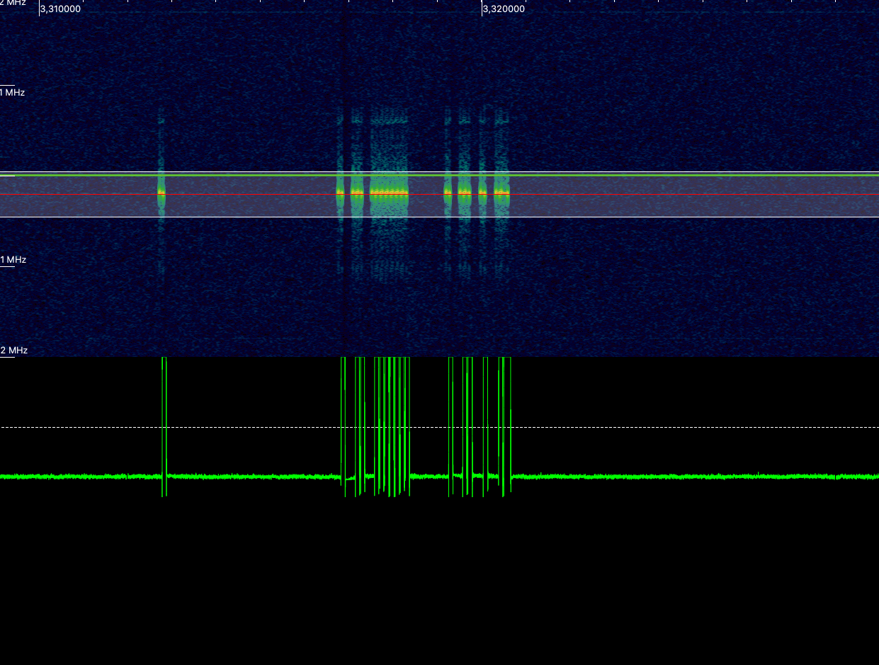
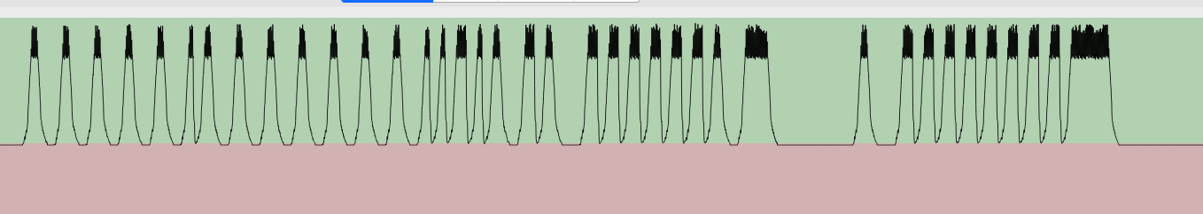
We are developing window contacts and sensors to detects the position of the window handle. For one of our customers we need to transmit EnOcean packets. The EnOcean packets must be ASK(OOK) modulated with a bitrate of 125kbit/s. 

We can transmit these types of packets with a CC1101 easily, but with the CC1310 it is not possible.

Do we have to use a different transceiver for this or is there any chance to transmit these packets with a CC1310? 

We only have to transmit these packets - receiving is not necessary!

  • Hi Thomas, 

    Assigning an expert to comment. 

    Thanks, 
    Elin

  • Hi Thomas,

    I'm currently looking into this and will get back to you as soon as I got an answer.

  • Hi Thomas, 

    I have checked with the radio group and they confirmed that 125 kbps in TX should be possible but from the RX side, you are limited somewhere around 10-20 kbps. 

  • Thanks for your reply. I think there is something wrong with the settings. I use the settings generated with the SmartRF Studio. I think something is wrong with HW_REG_OVERRIDE(0x6098,0x6E00) and 

    HW_REG_OVERRIDE(0x52B8,0x80A7)
    These settings are for ramping? 
    For the 125kbit/s baud rate they are not working.
    I couldn't find any documentation for these settings.
    Here are the complete settings generated by SmartRF Studio
    // TI-RTOS RF Mode Object
    RF_Mode RF_prop =
    {
        .rfMode = RF_MODE_PROPRIETARY_SUB_1,
        .cpePatchFxn = &rf_patch_cpe_genook,
        .mcePatchFxn = &rf_patch_mce_genook,
        .rfePatchFxn = &rf_patch_rfe_genook
    };
    
    
    // Overrides for CMD_PROP_RADIO_DIV_SETUP
    uint32_t pOverrides[] =
    {
        // override_use_patch_prop_genook_nrz.xml
        // PHY: Use MCE RAM patch, RFE RAM patch
        MCE_RFE_OVERRIDE(1,0,0,1,0,0),
        // override_synth_prop_863_930_div5.xml
        // Synth: Set recommended RTRIM to 7
        HW_REG_OVERRIDE(0x4038,0x0037),
        // Synth: Set Fref to 4 MHz
        (uint32_t)0x000684A3,
        // Synth: Configure fine calibration setting
        HW_REG_OVERRIDE(0x4020,0x7F00),
        // Synth: Configure fine calibration setting
        HW_REG_OVERRIDE(0x4064,0x0040),
        // Synth: Configure fine calibration setting
        (uint32_t)0xB1070503,
        // Synth: Configure fine calibration setting
        (uint32_t)0x05330523,
        // Synth: Set loop bandwidth after lock to 20 kHz
        (uint32_t)0x0A480583,
        // Synth: Set loop bandwidth after lock to 20 kHz
        (uint32_t)0x7AB80603,
        // Synth: Configure VCO LDO (in ADI1, set VCOLDOCFG=0x9F to use voltage input reference)
        ADI_REG_OVERRIDE(1,4,0x9F),
        // Synth: Configure synth LDO (in ADI1, set SLDOCTL0.COMP_CAP=1)
        ADI_HALFREG_OVERRIDE(1,7,0x4,0x4),
        // Synth: Use 24 MHz XOSC as synth clock, enable extra PLL filtering
        (uint32_t)0x02010403,
        // Synth: Configure extra PLL filtering
        (uint32_t)0x00108463,
        // Synth: Increase synth programming timeout (0x04B0 RAT ticks = 300 us)
        (uint32_t)0x04B00243,
        // override_synth_disable_bias_div5.xml
        // Synth: Set divider bias to disabled
        HW32_ARRAY_OVERRIDE(0x405C,1),
        // Synth: Set divider bias to disabled (specific for loDivider=5)
        (uint32_t)0x18000200,
        // override_phy_rx_aaf_bw_0xd.xml
        // Rx: Set anti-aliasing filter bandwidth to 0xD (in ADI0, set IFAMPCTL3[7:4]=0xD)
        ADI_HALFREG_OVERRIDE(0,61,0xF,0xD),
        // override_phy_agc_reflevel_0x19.xml
        // Rx: Set AGC reference level to 0x19
        HW_REG_OVERRIDE(0x6088,0x0019),
        // override_phy_ook_rx.xml
        // Rx: Set LNA bias current trim offset to 3
        (uint32_t)0x00038883,
        // Rx: Freeze RSSI on sync found event
        HW_REG_OVERRIDE(0x6084,0x35F1),
        // override_phy_ook_rx_filter_iir_k_1div4.xml
        // Rx: Set data filter to IIR, k=1/4. Explanation: 0x0000: k=1 (no filter), 0x0001: k=1/2, 0x0002: k=1/4, 0x0003: k=1/8.
        HW_REG_OVERRIDE(0x5204,0x0002),
        // override_phy_ook_tx_power_10dbm.xml
        // Tx: Ramp symbol shape to +10 dBm PA level (0x6E00). Explanation: min PA level=0x6100, ..., max PA level=0x7200. Bits [15:13] sets wait delay per PA ramp level. Bits[12:8] sets number of PA levels to use from ramp LUT (range 1-18). Bits[7:0] reserved.
        HW_REG_OVERRIDE(0x6098,0x6E00),
        // Tx: Set symbol duty-cycle delay before symbol ramp-down to 0xA7 (=168). This means symbol ramp down will begin after reaching (T_symbol/2) plus wait a delay of (167/2)=83 us.
        HW_REG_OVERRIDE(0x52B8,0x80A7),
        // override_phy_rx_rssi_offset_5db.xml
        // Rx: Set RSSI offset to adjust reported RSSI by +5 dB (default: 0), trimmed for external bias and differential configuration
        (uint32_t)0x00FB88A3,
        (uint32_t)0xFFFFFFFF
    };
    
    
    // CMD_PROP_RADIO_DIV_SETUP
    // Proprietary Mode Radio Setup Command for All Frequency Bands
    rfc_CMD_PROP_RADIO_DIV_SETUP_t RF_cmdPropRadioDivSetup =
    {
        .commandNo = 0x3807,
        .status = 0x0000,
        .pNextOp = 0, // INSERT APPLICABLE POINTER: (uint8_t*)&xxx
        .startTime = 0x00000000,
        .startTrigger.triggerType = 0x0,
        .startTrigger.bEnaCmd = 0x0,
        .startTrigger.triggerNo = 0x0,
        .startTrigger.pastTrig = 0x0,
        .condition.rule = 0x1,
        .condition.nSkip = 0x0,
        .modulation.modType = 0x2,
        .modulation.deviation = 0x0,
        .symbolRate.preScale = 0xF,
        .symbolRate.rateWord = 0x14000,
        .symbolRate.decimMode = 0x0,
        .rxBw = 0x2B,
        .preamConf.nPreamBytes = 0x4,
        .preamConf.preamMode = 0x0,
        .formatConf.nSwBits = 0x20,
        .formatConf.bBitReversal = 0x0,
        .formatConf.bMsbFirst = 0x1,
        .formatConf.fecMode = 0x0,
        .formatConf.whitenMode = 0x0,
        .config.frontEndMode = 0x0,
        .config.biasMode = 0x1,
        .config.analogCfgMode = 0x0,
        .config.bNoFsPowerUp = 0x0,
        .txPower = 0x38D3,
        .pRegOverride = pOverrides,
        .centerFreq = 0x0364,
        .intFreq = 0x8000,
        .loDivider = 0x05
    };
    
    
    // CMD_FS
    // Frequency Synthesizer Programming Command
    rfc_CMD_FS_t RF_cmdFs =
    {
        .commandNo = 0x0803,
        .status = 0x0000,
        .pNextOp = 0, // INSERT APPLICABLE POINTER: (uint8_t*)&xxx
        .startTime = 0x00000000,
        .startTrigger.triggerType = 0x0,
        .startTrigger.bEnaCmd = 0x0,
        .startTrigger.triggerNo = 0x0,
        .startTrigger.pastTrig = 0x0,
        .condition.rule = 0x1,
        .condition.nSkip = 0x0,
        .frequency = 0x0364,
        .fractFreq = 0x4CCD,
        .synthConf.bTxMode = 0x0,
        .synthConf.refFreq = 0x0,
        .__dummy0 = 0x00,
        .__dummy1 = 0x00,
        .__dummy2 = 0x00,
        .__dummy3 = 0x0000
    };
    
    
    // CMD_PROP_TX
    // Proprietary Mode Transmit Command
    rfc_CMD_PROP_TX_t RF_cmdPropTx =
    {
        .commandNo = 0x3801,
        .status = 0x0000,
        .pNextOp = 0, // INSERT APPLICABLE POINTER: (uint8_t*)&xxx
        .startTime = 0x00000000,
        .startTrigger.triggerType = 0x0,
        .startTrigger.bEnaCmd = 0x0,
        .startTrigger.triggerNo = 0x0,
        .startTrigger.pastTrig = 0x0,
        .condition.rule = 0x1,
        .condition.nSkip = 0x0,
        .pktConf.bFsOff = 0x0,
        .pktConf.bUseCrc = 0x1,
        .pktConf.bVarLen = 0x1,
        .pktLen = 0x14,
        .syncWord = 0x930B51DE,
        .pPkt = 0 // INSERT APPLICABLE POINTER: (uint8_t*)&xxx
    };
    

  • Hi Thomas, 

    Are you seeing any output at all if you are observing the RSSI (using for example the continuous RX view in SmartRF Studio) or is there no output at all? 

  • Also, could you share the CC1101 settings you use when testing this (and to run 125 kbps in the first place)?

  • I can see, that the CC1310 is transmitting one pulse (width ~84us) with these settings:


    If I only change the baudrate to 4.8kbaud then the signal looks like this:

    If I change HW_REG_OVERRIDE(0x6098,0x6E00) to HW_REG_OVERRIDE(0x6098,0x0E00) the output looks like this:


    Here are the cc1101 settings:

    const uint8_t cc1101_settings[] =
    {
    		0x06, // 00 GDO2
    		0x2E, // 01 GDO1
    		0x0D, // 02 GDO0
    		0x47, // 03 FIFOTHR
    		0xAA, // 04 SYNC1
    		0xAA, // 05 SYNC0
    		0x15, // 06 PKTLEN
    		0x04, // 07 PKTCTRL1
    		0x00, // 08 PKTCTRL0
    		0x00, // 09 ADDR
    		0x00, // 0A CHANNR
    		0x08, // 0B FSCTRL1
    		0x00, // 0C FSCTRL0
    		0x21, // 0D FREQ2
    		0x65, // 0E FREQ1
    		0x6A, // 0F FREQ0
    
    		0x5C, // 10 MDMCFG4
    		0x3B, // 11 MDMCFG3
    		0x30, // 12 MDMCFG2
    		0x03, // 13 MDMCFG1
    
    		0x61, // 14 MDMCFG0
    		0x24, // 15 DEVIATN
    		0x07, // 16 MCSM2
    		0x0C, // 17 MCSM1
    		0x18, // 18 MCSM0
    		0x2E, // 19 FOCCFG
    		0xBF, // 1A BSCFG
    		0x03, // 1B AGCCTRL2
    		0x00, // 1C AGCCTRL1
    		0x91, // 1D AGCCTRL0
    		0x87, // 1E WOREVT1
    		0x6B, // 1F WOREVT0
    		0xFB, // 20 WORCTRL
    		0xB6, // 21 FREND1
    		0x11, // 22 FREND0
    		0xEA, // 23 FSCAL3
    		0x2A, // 24 FSCAL2
    		0x00, // 25 FSCAL1
    		0x1F, // 26 FSCAL0
    		0x41, // 27 RCCTRL1
    		0x00, // 28 RCCTRL0
    		0x59, // 29 FSTEST
    		0x7F, // 2A PTEST
    		0x3F, // 2B AGCTST
    		0x81, // 2C TEST2
    		0x35, // 2D TEST1
    		0x09 // 2E TEST0
    };

  • Hi Thomas, 

    I asked the radio team to look closer at it and it seems that the CC1310 firmware does not allow for this today due to the PA ramping scheme used. While the PHY could potentially be updated to support higher data rates, it is currently no plan to do so I'm afraid.

  • Oh these are bad news...

    Is there no workaround? I don't need PA ramping with different levels

    If I play a little with the values of register 0x6098 and 0x52B8 something happens. 

    For example the output signal looks like this:

    But the timing is not correct. The smallest pulse is 32us long (should be 8us)

  • Hi Thomas, 

    There is no simple workaround that I could propose for you to test out "as is" from what is in the SDK. What I got from the modem team is that this is likely a patch related fix to get working at these speeds but the wait times now a day is long so the chance to get a new patch out in short term is not likely (in the end, it boils down to the business case for it).

    I have however made them aware of it and will do my best to get it on the CBL.