This thread has been locked.

If you have a related question, please click the "Ask a related question" button in the top right corner. The newly created question will be automatically linked to this question.

CC1121: RSSI appended to the packet is abnormal

Part Number: CC1121
Other Parts Discussed in Thread: CC1120

Hi,

My customers send and receive using products with CC1121.
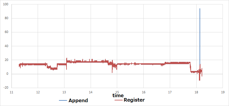
CC1121 is set to append RSSI to the packet.(PKT_CFG1.APPEND_STATUS=1)
After communicating for a few minutes, the RSSI value of the packet will be abnormal.

They compared packet's RSSI value with register's RSSI value. It is usually the same value, but sometimes the packet's value becomes abnormal.

Question 1:
How is the RSSI value of a packet calculated? Is it the same as the register value?

Question 2:
Their product outputs the RSSI of the packet to the LCD. They want this value to be normal. Would you tell me the solution?

Register settings (SmartRF Studio & EVM)

Tx

TX_CC1120.xml
// Rf settings for CC1120
RF_SETTINGS code rfSettings = {
    0xB0,  // IOCFG3                GPIO3 IO Pin Configuration
    0x06,  // IOCFG2                GPIO2 IO Pin Configuration
    0xB0,  // IOCFG1                GPIO1 IO Pin Configuration
    0x40,  // IOCFG0                GPIO0 IO Pin Configuration
    0x08,  // SYNC_CFG1             Sync Word Detection Configuration Reg. 1
    0x17,  // SYNC_CFG0             Sync Word Length Configuration Reg. 0
    0x9A,  // DEVIATION_M           Frequency Deviation Configuration
    0x0D,  // MODCFG_DEV_E          Modulation Format and Frequency Deviation Configur..
    0x1C,  // DCFILT_CFG            Digital DC Removal Configuration
    0x14,  // PREAMBLE_CFG1         Preamble Length Configuration Reg. 1
    0x2A,  // PREAMBLE_CFG0         Preamble Detection Configuration Reg. 0
    0x40,  // FREQ_IF_CFG           RX Mixer Frequency Configuration
    0x00,  // IQIC                  Digital Image Channel Compensation Configuration
    0x02,  // CHAN_BW               Channel Filter Configuration
    0x46,  // MDMCFG1               General Modem Parameter Configuration Reg. 1
    0x05,  // MDMCFG0               General Modem Parameter Configuration Reg. 0
    0x99,  // SYMBOL_RATE2          Symbol Rate Configuration Exponent and Mantissa [1..
    0x99,  // SYMBOL_RATE1          Symbol Rate Configuration Mantissa [15:8]
    0x9A,  // SYMBOL_RATE0          Symbol Rate Configuration Mantissa [7:0]
    0x36,  // AGC_REF               AGC Reference Level Configuration
    0x19,  // AGC_CS_THR            Carrier Sense Threshold Configuration
    0x00,  // AGC_GAIN_ADJUST       RSSI Offset Configuration
    0x91,  // AGC_CFG3              Automatic Gain Control Configuration Reg. 3
    0x20,  // AGC_CFG2              Automatic Gain Control Configuration Reg. 2
    0xA9,  // AGC_CFG1              Automatic Gain Control Configuration Reg. 1
    0xCF,  // AGC_CFG0              Automatic Gain Control Configuration Reg. 0
    0x00,  // FIFO_CFG              FIFO Configuration
    0x00,  // DEV_ADDR              Device Address Configuration
    0x03,  // SETTLING_CFG          Frequency Synthesizer Calibration and Settling Con..
    0x12,  // FS_CFG                Frequency Synthesizer Configuration
    0x08,  // WOR_CFG1              eWOR Configuration Reg. 1
    0x21,  // WOR_CFG0              eWOR Configuration Reg. 0
    0x00,  // WOR_EVENT0_MSB        Event 0 Configuration MSB
    0x00,  // WOR_EVENT0_LSB        Event 0 Configuration LSB
    0x04,  // PKT_CFG2              Packet Configuration Reg. 2
    0x45,  // PKT_CFG1              Packet Configuration Reg. 1
    0x20,  // PKT_CFG0              Packet Configuration Reg. 0
    0x0F,  // RFEND_CFG1            RFEND Configuration Reg. 1
    0x00,  // RFEND_CFG0            RFEND Configuration Reg. 0
    0x7F,  // PA_CFG2               Power Amplifier Configuration Reg. 2
    0x56,  // PA_CFG1               Power Amplifier Configuration Reg. 1
    0x7B,  // PA_CFG0               Power Amplifier Configuration Reg. 0
    0xFF,  // PKT_LEN               Packet Length Configuration
    0x00,  // IF_MIX_CFG            IF Mix Configuration
    0x22,  // FREQOFF_CFG           Frequency Offset Correction Configuration
    0x0B,  // TOC_CFG               Timing Offset Correction Configuration
    0x00,  // MARC_SPARE            MARC Spare
    0x00,  // ECG_CFG               External Clock Frequency Configuration
    0x00,  // CFM_DATA_CFG          Custom frequency modulation enable
    0x01,  // EXT_CTRL              External Control Configuration
    0x00,  // RCCAL_FINE            RC Oscillator Calibration Fine
    0x00,  // RCCAL_COARSE          RC Oscillator Calibration Coarse
    0x00,  // RCCAL_OFFSET          RC Oscillator Calibration Clock Offset
    0x00,  // FREQOFF1              Frequency Offset MSB
    0x00,  // FREQOFF0              Frequency Offset LSB
    0x73,  // FREQ2                 Frequency Configuration [23:16]
    0xF9,  // FREQ1                 Frequency Configuration [15:8]
    0x99,  // FREQ0                 Frequency Configuration [7:0]
    0x02,  // IF_ADC2               Analog to Digital Converter Configuration Reg. 2
    0xA6,  // IF_ADC1               Analog to Digital Converter Configuration Reg. 1
    0x04,  // IF_ADC0               Analog to Digital Converter Configuration Reg. 0
    0x00,  // FS_DIG1               Frequency Synthesizer Digital Reg. 1
    0x5F,  // FS_DIG0               Frequency Synthesizer Digital Reg. 0
    0x00,  // FS_CAL3               Frequency Synthesizer Calibration Reg. 3
    0x20,  // FS_CAL2               Frequency Synthesizer Calibration Reg. 2
    0x40,  // FS_CAL1               Frequency Synthesizer Calibration Reg. 1
    0x0E,  // FS_CAL0               Frequency Synthesizer Calibration Reg. 0
    0x28,  // FS_CHP                Frequency Synthesizer Charge Pump Configuration
    0x03,  // FS_DIVTWO             Frequency Synthesizer Divide by 2
    0x00,  // FS_DSM1               FS Digital Synthesizer Module Configuration Reg. 1
    0x33,  // FS_DSM0               FS Digital Synthesizer Module Configuration Reg. 0
    0xFF,  // FS_DVC1               Frequency Synthesizer Divider Chain Configuration ..
    0x17,  // FS_DVC0               Frequency Synthesizer Divider Chain Configuration ..
    0x00,  // FS_LBI                Frequency Synthesizer Local Bias Configuration
    0x50,  // FS_PFD                Frequency Synthesizer Phase Frequency Detector Con..
    0x6E,  // FS_PRE                Frequency Synthesizer Prescaler Configuration
    0x14,  // FS_REG_DIV_CML        Frequency Synthesizer Divider Regulator Configurat..
    0xAC,  // FS_SPARE              Frequency Synthesizer Spare
    0x14,  // FS_VCO4               FS Voltage Controlled Oscillator Configuration Reg..
    0x00,  // FS_VCO3               FS Voltage Controlled Oscillator Configuration Reg..
    0x00,  // FS_VCO2               FS Voltage Controlled Oscillator Configuration Reg..
    0x00,  // FS_VCO1               FS Voltage Controlled Oscillator Configuration Reg..
    0xB4,  // FS_VCO0               FS Voltage Controlled Oscillator Configuration Reg..
    0x00,  // GBIAS6                Global Bias Configuration Reg. 6
    0x02,  // GBIAS5                Global Bias Configuration Reg. 5
    0x00,  // GBIAS4                Global Bias Configuration Reg. 4
    0x00,  // GBIAS3                Global Bias Configuration Reg. 3
    0x10,  // GBIAS2                Global Bias Configuration Reg. 2
    0x00,  // GBIAS1                Global Bias Configuration Reg. 1
    0x00,  // GBIAS0                Global Bias Configuration Reg. 0
    0x01,  // IFAMP                 Intermediate Frequency Amplifier Configuration
    0x01,  // LNA                   Low Noise Amplifier Configuration
    0x01,  // RXMIX                 RX Mixer Configuration
    0x0E,  // XOSC5                 Crystal Oscillator Configuration Reg. 5
    0xA0,  // XOSC4                 Crystal Oscillator Configuration Reg. 4
    0x03,  // XOSC3                 Crystal Oscillator Configuration Reg. 3
    0x04,  // XOSC2                 Crystal Oscillator Configuration Reg. 2
    0x03,  // XOSC1                 Crystal Oscillator Configuration Reg. 1
    0x00,  // XOSC0                 Crystal Oscillator Configuration Reg. 0
    0x00,  // ANALOG_SPARE          Analog Spare
    0x00,  // PA_CFG3               Power Amplifier Configuration Reg. 3
    0x00,  // WOR_TIME1             eWOR Timer Counter Value MSB
    0x00,  // WOR_TIME0             eWOR Timer Counter Value LSB
    0x00,  // WOR_CAPTURE1          eWOR Timer Capture Value MSB
    0x00,  // WOR_CAPTURE0          eWOR Timer Capture Value LSB
    0x00,  // BIST                  MARC Built-In Self-Test
    0x00,  // DCFILTOFFSET_I1       DC Filter Offset I MSB
    0x00,  // DCFILTOFFSET_I0       DC Filter Offset I LSB
    0x00,  // DCFILTOFFSET_Q1       DC Filter Offset Q MSB
    0x00,  // DCFILTOFFSET_Q0       DC Filter Offset Q LSB
    0x00,  // IQIE_I1               IQ Imbalance Value I MSB
    0x00,  // IQIE_I0               IQ Imbalance Value I LSB
    0x00,  // IQIE_Q1               IQ Imbalance Value Q MSB
    0x00,  // IQIE_Q0               IQ Imbalance Value Q LSB
    0x80,  // RSSI1                 Received Signal Strength Indicator Reg. 1
    0x00,  // RSSI0                 Received Signal Strength Indicator Reg.0
    0x41,  // MARCSTATE             MARC State
    0x00,  // LQI_VAL               Link Quality Indicator Value
    0xFF,  // PQT_SYNC_ERR          Preamble and Sync Word Error
    0x00,  // DEM_STATUS            Demodulator Status
    0x00,  // FREQOFF_EST1          Frequency Offset Estimate MSB
    0x00,  // FREQOFF_EST0          Frequency Offset Estimate LSB
    0x00,  // AGC_GAIN3             Automatic Gain Control Reg. 3
    0xD1,  // AGC_GAIN2             Automatic Gain Control Reg. 2
    0x00,  // AGC_GAIN1             Automatic Gain Control Reg. 1
    0x3F,  // AGC_GAIN0             Automatic Gain Control Reg. 0
    0x00,  // CFM_RX_DATA_OUT       Custom Frequency Modulation RX Data
    0x00,  // CFM_TX_DATA_IN        Custom Frequency Modulation TX Data
    0x30,  // ASK_SOFT_RX_DATA      ASK Soft Decision Output
    0x7F,  // RNDGEN                Random Number Generator Value
    0x00,  // MAGN2                 Signal Magnitude after CORDIC [16]
    0x00,  // MAGN1                 Signal Magnitude after CORDIC [15:8]
    0x00,  // MAGN0                 Signal Magnitude after CORDIC [7:0]
    0x00,  // ANG1                  Signal Angular after CORDIC [9:8]
    0x00,  // ANG0                  Signal Angular after CORDIC [7:0]
    0x08,  // CHFILT_I2             Channel Filter Data Real Part [18:16]
    0x00,  // CHFILT_I1             Channel Filter Data Real Part [15:8]
    0x00,  // CHFILT_I0             Channel Filter Data Real Part [7:0]
    0x00,  // CHFILT_Q2             Channel Filter Data Imaginary Part [18:16]
    0x00,  // CHFILT_Q1             Channel Filter Data Imaginary Part [15:8]
    0x00,  // CHFILT_Q0             Channel Filter Data Imaginary Part [7:0]
    0x00,  // GPIO_STATUS           General Purpose Input/Output Status
    0x01,  // FSCAL_CTRL            Frequency Synthesizer Calibration Control
    0x00,  // PHASE_ADJUST          Frequency Synthesizer Phase Adjust
    0x48,  // PARTNUMBER            Part Number
    0x21,  // PARTVERSION           Part Revision
    0x00,  // SERIAL_STATUS         Serial Status
    0x10,  // MODEM_STATUS1         Modem Status Reg. 1
    0x00,  // MODEM_STATUS0         Modem Status Reg. 0
    0x00,  // MARC_STATUS1          MARC Status Reg. 1
    0x00,  // MARC_STATUS0          MARC Status Reg. 0
    0x00,  // PA_IFAMP_TEST         Power Amplifier Intermediate Frequency Amplifier T..
    0x00,  // FSRF_TEST             Frequency Synthesizer Test
    0x00,  // PRE_TEST              Frequency Synthesizer Prescaler Test
    0x00,  // PRE_OVR               Frequency Synthesizer Prescaler Override
    0x00,  // ADC_TEST              Analog to Digital Converter Test
    0x0B,  // DVC_TEST              Digital Divider Chain Test
    0x40,  // ATEST                 Analog Test
    0x00,  // ATEST_LVDS            Analog Test LVDS
    0x00,  // ATEST_MODE            Analog Test Mode
    0x3C,  // XOSC_TEST1            Crystal Oscillator Test Reg. 1
    0x00,  // XOSC_TEST0            Crystal Oscillator Test Reg. 0
    0x00,  // RXFIRST               RX FIFO Pointer First Entry
    0x00,  // TXFIRST               TX FIFO Pointer First Entry
    0x00,  // RXLAST                RX FIFO Pointer Last Entry
    0x00,  // TXLAST                TX FIFO Pointer Last Entry
    0x00,  // NUM_TXBYTES           TX FIFO Status
    0x00,  // NUM_RXBYTES           RX FIFO Status
    0x0F,  // FIFO_NUM_TXBYTES      TX FIFO Status
    0x00,  // FIFO_NUM_RXBYTES      RX FIFO Status
};

Rx

RX_CC1120.xml
// Rf settings for CC1120
RF_SETTINGS code rfSettings = {
    0xB0,  // IOCFG3                GPIO3 IO Pin Configuration
    0x06,  // IOCFG2                GPIO2 IO Pin Configuration
    0xB0,  // IOCFG1                GPIO1 IO Pin Configuration
    0x40,  // IOCFG0                GPIO0 IO Pin Configuration
    0x08,  // SYNC_CFG1             Sync Word Detection Configuration Reg. 1
    0x17,  // SYNC_CFG0             Sync Word Length Configuration Reg. 0
    0x9A,  // DEVIATION_M           Frequency Deviation Configuration
    0x0D,  // MODCFG_DEV_E          Modulation Format and Frequency Deviation Configur..
    0x1C,  // DCFILT_CFG            Digital DC Removal Configuration
    0x14,  // PREAMBLE_CFG1         Preamble Length Configuration Reg. 1
    0x2A,  // PREAMBLE_CFG0         Preamble Detection Configuration Reg. 0
    0x40,  // FREQ_IF_CFG           RX Mixer Frequency Configuration
    0x00,  // IQIC                  Digital Image Channel Compensation Configuration
    0x02,  // CHAN_BW               Channel Filter Configuration
    0x46,  // MDMCFG1               General Modem Parameter Configuration Reg. 1
    0x05,  // MDMCFG0               General Modem Parameter Configuration Reg. 0
    0x99,  // SYMBOL_RATE2          Symbol Rate Configuration Exponent and Mantissa [1..
    0x99,  // SYMBOL_RATE1          Symbol Rate Configuration Mantissa [15:8]
    0x9A,  // SYMBOL_RATE0          Symbol Rate Configuration Mantissa [7:0]
    0x36,  // AGC_REF               AGC Reference Level Configuration
    0x19,  // AGC_CS_THR            Carrier Sense Threshold Configuration
    0x00,  // AGC_GAIN_ADJUST       RSSI Offset Configuration
    0x91,  // AGC_CFG3              Automatic Gain Control Configuration Reg. 3
    0x20,  // AGC_CFG2              Automatic Gain Control Configuration Reg. 2
    0xA9,  // AGC_CFG1              Automatic Gain Control Configuration Reg. 1
    0xCF,  // AGC_CFG0              Automatic Gain Control Configuration Reg. 0
    0x00,  // FIFO_CFG              FIFO Configuration
    0x00,  // DEV_ADDR              Device Address Configuration
    0x03,  // SETTLING_CFG          Frequency Synthesizer Calibration and Settling Con..
    0x12,  // FS_CFG                Frequency Synthesizer Configuration
    0x08,  // WOR_CFG1              eWOR Configuration Reg. 1
    0x21,  // WOR_CFG0              eWOR Configuration Reg. 0
    0x00,  // WOR_EVENT0_MSB        Event 0 Configuration MSB
    0x00,  // WOR_EVENT0_LSB        Event 0 Configuration LSB
    0x04,  // PKT_CFG2              Packet Configuration Reg. 2
    0x45,  // PKT_CFG1              Packet Configuration Reg. 1
    0x20,  // PKT_CFG0              Packet Configuration Reg. 0
    0x0F,  // RFEND_CFG1            RFEND Configuration Reg. 1
    0x00,  // RFEND_CFG0            RFEND Configuration Reg. 0
    0x7F,  // PA_CFG2               Power Amplifier Configuration Reg. 2
    0x56,  // PA_CFG1               Power Amplifier Configuration Reg. 1
    0x7B,  // PA_CFG0               Power Amplifier Configuration Reg. 0
    0xFF,  // PKT_LEN               Packet Length Configuration
    0x00,  // IF_MIX_CFG            IF Mix Configuration
    0x22,  // FREQOFF_CFG           Frequency Offset Correction Configuration
    0x0B,  // TOC_CFG               Timing Offset Correction Configuration
    0x00,  // MARC_SPARE            MARC Spare
    0x00,  // ECG_CFG               External Clock Frequency Configuration
    0x00,  // CFM_DATA_CFG          Custom frequency modulation enable
    0x01,  // EXT_CTRL              External Control Configuration
    0x00,  // RCCAL_FINE            RC Oscillator Calibration Fine
    0x00,  // RCCAL_COARSE          RC Oscillator Calibration Coarse
    0x00,  // RCCAL_OFFSET          RC Oscillator Calibration Clock Offset
    0x00,  // FREQOFF1              Frequency Offset MSB
    0x00,  // FREQOFF0              Frequency Offset LSB
    0x73,  // FREQ2                 Frequency Configuration [23:16]
    0xF9,  // FREQ1                 Frequency Configuration [15:8]
    0x99,  // FREQ0                 Frequency Configuration [7:0]
    0x02,  // IF_ADC2               Analog to Digital Converter Configuration Reg. 2
    0xA6,  // IF_ADC1               Analog to Digital Converter Configuration Reg. 1
    0x04,  // IF_ADC0               Analog to Digital Converter Configuration Reg. 0
    0x00,  // FS_DIG1               Frequency Synthesizer Digital Reg. 1
    0x5F,  // FS_DIG0               Frequency Synthesizer Digital Reg. 0
    0x00,  // FS_CAL3               Frequency Synthesizer Calibration Reg. 3
    0x20,  // FS_CAL2               Frequency Synthesizer Calibration Reg. 2
    0x40,  // FS_CAL1               Frequency Synthesizer Calibration Reg. 1
    0x0E,  // FS_CAL0               Frequency Synthesizer Calibration Reg. 0
    0x28,  // FS_CHP                Frequency Synthesizer Charge Pump Configuration
    0x03,  // FS_DIVTWO             Frequency Synthesizer Divide by 2
    0x00,  // FS_DSM1               FS Digital Synthesizer Module Configuration Reg. 1
    0x33,  // FS_DSM0               FS Digital Synthesizer Module Configuration Reg. 0
    0xFF,  // FS_DVC1               Frequency Synthesizer Divider Chain Configuration ..
    0x17,  // FS_DVC0               Frequency Synthesizer Divider Chain Configuration ..
    0x00,  // FS_LBI                Frequency Synthesizer Local Bias Configuration
    0x50,  // FS_PFD                Frequency Synthesizer Phase Frequency Detector Con..
    0x6E,  // FS_PRE                Frequency Synthesizer Prescaler Configuration
    0x14,  // FS_REG_DIV_CML        Frequency Synthesizer Divider Regulator Configurat..
    0xAC,  // FS_SPARE              Frequency Synthesizer Spare
    0x14,  // FS_VCO4               FS Voltage Controlled Oscillator Configuration Reg..
    0x00,  // FS_VCO3               FS Voltage Controlled Oscillator Configuration Reg..
    0x00,  // FS_VCO2               FS Voltage Controlled Oscillator Configuration Reg..
    0x00,  // FS_VCO1               FS Voltage Controlled Oscillator Configuration Reg..
    0xB4,  // FS_VCO0               FS Voltage Controlled Oscillator Configuration Reg..
    0x00,  // GBIAS6                Global Bias Configuration Reg. 6
    0x02,  // GBIAS5                Global Bias Configuration Reg. 5
    0x00,  // GBIAS4                Global Bias Configuration Reg. 4
    0x00,  // GBIAS3                Global Bias Configuration Reg. 3
    0x10,  // GBIAS2                Global Bias Configuration Reg. 2
    0x00,  // GBIAS1                Global Bias Configuration Reg. 1
    0x00,  // GBIAS0                Global Bias Configuration Reg. 0
    0x01,  // IFAMP                 Intermediate Frequency Amplifier Configuration
    0x01,  // LNA                   Low Noise Amplifier Configuration
    0x01,  // RXMIX                 RX Mixer Configuration
    0x0E,  // XOSC5                 Crystal Oscillator Configuration Reg. 5
    0xA0,  // XOSC4                 Crystal Oscillator Configuration Reg. 4
    0x03,  // XOSC3                 Crystal Oscillator Configuration Reg. 3
    0x04,  // XOSC2                 Crystal Oscillator Configuration Reg. 2
    0x03,  // XOSC1                 Crystal Oscillator Configuration Reg. 1
    0x00,  // XOSC0                 Crystal Oscillator Configuration Reg. 0
    0x00,  // ANALOG_SPARE          Analog Spare
    0x00,  // PA_CFG3               Power Amplifier Configuration Reg. 3
    0x00,  // WOR_TIME1             eWOR Timer Counter Value MSB
    0x00,  // WOR_TIME0             eWOR Timer Counter Value LSB
    0x00,  // WOR_CAPTURE1          eWOR Timer Capture Value MSB
    0x00,  // WOR_CAPTURE0          eWOR Timer Capture Value LSB
    0x00,  // BIST                  MARC Built-In Self-Test
    0x00,  // DCFILTOFFSET_I1       DC Filter Offset I MSB
    0x00,  // DCFILTOFFSET_I0       DC Filter Offset I LSB
    0x00,  // DCFILTOFFSET_Q1       DC Filter Offset Q MSB
    0x00,  // DCFILTOFFSET_Q0       DC Filter Offset Q LSB
    0x00,  // IQIE_I1               IQ Imbalance Value I MSB
    0x00,  // IQIE_I0               IQ Imbalance Value I LSB
    0x00,  // IQIE_Q1               IQ Imbalance Value Q MSB
    0x00,  // IQIE_Q0               IQ Imbalance Value Q LSB
    0x80,  // RSSI1                 Received Signal Strength Indicator Reg. 1
    0x00,  // RSSI0                 Received Signal Strength Indicator Reg.0
    0x41,  // MARCSTATE             MARC State
    0x00,  // LQI_VAL               Link Quality Indicator Value
    0xFF,  // PQT_SYNC_ERR          Preamble and Sync Word Error
    0x00,  // DEM_STATUS            Demodulator Status
    0x00,  // FREQOFF_EST1          Frequency Offset Estimate MSB
    0x00,  // FREQOFF_EST0          Frequency Offset Estimate LSB
    0x00,  // AGC_GAIN3             Automatic Gain Control Reg. 3
    0xD1,  // AGC_GAIN2             Automatic Gain Control Reg. 2
    0x00,  // AGC_GAIN1             Automatic Gain Control Reg. 1
    0x3F,  // AGC_GAIN0             Automatic Gain Control Reg. 0
    0x00,  // CFM_RX_DATA_OUT       Custom Frequency Modulation RX Data
    0x00,  // CFM_TX_DATA_IN        Custom Frequency Modulation TX Data
    0x30,  // ASK_SOFT_RX_DATA      ASK Soft Decision Output
    0x7F,  // RNDGEN                Random Number Generator Value
    0x00,  // MAGN2                 Signal Magnitude after CORDIC [16]
    0x00,  // MAGN1                 Signal Magnitude after CORDIC [15:8]
    0x00,  // MAGN0                 Signal Magnitude after CORDIC [7:0]
    0x00,  // ANG1                  Signal Angular after CORDIC [9:8]
    0x00,  // ANG0                  Signal Angular after CORDIC [7:0]
    0x08,  // CHFILT_I2             Channel Filter Data Real Part [18:16]
    0x00,  // CHFILT_I1             Channel Filter Data Real Part [15:8]
    0x00,  // CHFILT_I0             Channel Filter Data Real Part [7:0]
    0x00,  // CHFILT_Q2             Channel Filter Data Imaginary Part [18:16]
    0x00,  // CHFILT_Q1             Channel Filter Data Imaginary Part [15:8]
    0x00,  // CHFILT_Q0             Channel Filter Data Imaginary Part [7:0]
    0x00,  // GPIO_STATUS           General Purpose Input/Output Status
    0x01,  // FSCAL_CTRL            Frequency Synthesizer Calibration Control
    0x00,  // PHASE_ADJUST          Frequency Synthesizer Phase Adjust
    0x48,  // PARTNUMBER            Part Number
    0x21,  // PARTVERSION           Part Revision
    0x00,  // SERIAL_STATUS         Serial Status
    0x10,  // MODEM_STATUS1         Modem Status Reg. 1
    0x00,  // MODEM_STATUS0         Modem Status Reg. 0
    0x00,  // MARC_STATUS1          MARC Status Reg. 1
    0x00,  // MARC_STATUS0          MARC Status Reg. 0
    0x00,  // PA_IFAMP_TEST         Power Amplifier Intermediate Frequency Amplifier T..
    0x00,  // FSRF_TEST             Frequency Synthesizer Test
    0x00,  // PRE_TEST              Frequency Synthesizer Prescaler Test
    0x00,  // PRE_OVR               Frequency Synthesizer Prescaler Override
    0x00,  // ADC_TEST              Analog to Digital Converter Test
    0x0B,  // DVC_TEST              Digital Divider Chain Test
    0x40,  // ATEST                 Analog Test
    0x00,  // ATEST_LVDS            Analog Test LVDS
    0x00,  // ATEST_MODE            Analog Test Mode
    0x3C,  // XOSC_TEST1            Crystal Oscillator Test Reg. 1
    0x00,  // XOSC_TEST0            Crystal Oscillator Test Reg. 0
    0x00,  // RXFIRST               RX FIFO Pointer First Entry
    0x00,  // TXFIRST               TX FIFO Pointer First Entry
    0x00,  // RXLAST                RX FIFO Pointer Last Entry
    0x00,  // TXLAST                TX FIFO Pointer Last Entry
    0x00,  // NUM_TXBYTES           TX FIFO Status
    0x00,  // NUM_RXBYTES           RX FIFO Status
    0x0F,  // FIFO_NUM_TXBYTES      TX FIFO Status
    0x00,  // FIFO_NUM_RXBYTES      RX FIFO Status
};

Regards,

Rei

  • The RSSI value in the RSSI register and the appended value will be the same if the packet is successfully received. I would assume that when you got a difference the packet is not received correctly.

    Also you should correct the RSSI with the RSSI offset (given in SmartRF Studio) to get the real RSSI.

  • Hi TER,

    We are checking the packet with CRC and the packet is being received correctly. Problem is that the value given to the packet is different from the register value. Why is the appended value different from the register value? I have confirmed with the default settings of SmartRF studio and CC1120, I suspect the register setting.

    I'm sorry, I accidentally pressed Resolved.

    Regards,
    Rei

  • The RSSI register is the only source for the RSSI value, if the attached RSSI value is different it sounds like something wrong with the receiption.

    - The data you present is not compensated for RSSI offset,. Could you show the same graph but with correct offset. What would be more interesting is to show the content of the packet with unexpected RSSI and compare with the packet s just before and after. I would need more details.

  • Hi TER, 

    Compensate RSSI Graphs


    Before and after wrong data

     data.csv

    The values before and after are normal. It's a very strange phenomenon..

    Have a great holiday!


    Regards, Rei

  • I was trying to look at the register settings but when I imported the RX settings into SmartRF Studio I got strange results. Could you check if th .xml file gives the wanted register settings?

  • Hi TER,

    Sorry, I got the xml file again.


    0447.RX_CC1120.xml
    <?xml version="1.0" encoding="ISO-8859-1"?>
    <!DOCTYPE configuration SYSTEM "C:/Program Files (x86)/Texas Instruments/SmartRF Tools/SmartRF Studio 7/config/xml/configdata.dtd"[]>
    <dcpanelconfiguration>
        <Devicename>CC1120</Devicename>
        <Description>Saved configuration data</Description>
        <registersettings>
            <Register>
                <Name>AGC_CFG0</Name>
                <Value>0xcf</Value>
            </Register>
            <Register>
                <Name>AGC_CFG1</Name>
                <Value>0xa9</Value>
            </Register>
            <Register>
                <Name>AGC_CS_THR</Name>
                <Value>0x19</Value>
            </Register>
            <Register>
                <Name>CHAN_BW</Name>
                <Value>0x02</Value>
            </Register>
            <Register>
                <Name>DCFILT_CFG</Name>
                <Value>0x1c</Value>
            </Register>
            <Register>
                <Name>DEVIATION_M</Name>
                <Value>0x9a</Value>
            </Register>
            <Register>
                <Name>FIFO_CFG</Name>
                <Value>0x00</Value>
            </Register>
            <Register>
                <Name>FREQ1</Name>
                <Value>0x40</Value>
            </Register>
            <Register>
                <Name>FREQ2</Name>
                <Value>0x73</Value>
            </Register>
            <Register>
                <Name>FREQOFF_CFG</Name>
                <Value>0x22</Value>
            </Register>
            <Register>
                <Name>FS_CAL0</Name>
                <Value>0x0e</Value>
            </Register>
            <Register>
                <Name>FS_CAL1</Name>
                <Value>0x40</Value>
            </Register>
            <Register>
                <Name>FS_CFG</Name>
                <Value>0x12</Value>
            </Register>
            <Register>
                <Name>FS_DIG0</Name>
                <Value>0x5f</Value>
            </Register>
            <Register>
                <Name>FS_DIG1</Name>
                <Value>0x00</Value>
            </Register>
            <Register>
                <Name>FS_DIVTWO</Name>
                <Value>0x03</Value>
            </Register>
            <Register>
                <Name>FS_DSM0</Name>
                <Value>0x33</Value>
            </Register>
            <Register>
                <Name>FS_DVC0</Name>
                <Value>0x17</Value>
            </Register>
            <Register>
                <Name>FS_PFD</Name>
                <Value>0x50</Value>
            </Register>
            <Register>
                <Name>FS_PRE</Name>
                <Value>0x6e</Value>
            </Register>
            <Register>
                <Name>FS_REG_DIV_CML</Name>
                <Value>0x14</Value>
            </Register>
            <Register>
                <Name>FS_SPARE</Name>
                <Value>0xac</Value>
            </Register>
            <Register>
                <Name>FS_VCO0</Name>
                <Value>0xb4</Value>
            </Register>
            <Register>
                <Name>IF_MIX_CFG</Name>
                <Value>0x00</Value>
            </Register>
            <Register>
                <Name>IOCFG0</Name>
                <Value>0x40</Value>
            </Register>
            <Register>
                <Name>IOCFG1</Name>
                <Value>0xb0</Value>
            </Register>
            <Register>
                <Name>IOCFG2</Name>
                <Value>0x06</Value>
            </Register>
            <Register>
                <Name>IOCFG3</Name>
                <Value>0xb0</Value>
            </Register>
            <Register>
                <Name>IQIC</Name>
                <Value>0x00</Value>
            </Register>
            <Register>
                <Name>MDMCFG0</Name>
                <Value>0x05</Value>
            </Register>
            <Register>
                <Name>MODCFG_DEV_E</Name>
                <Value>0x0d</Value>
            </Register>
            <Register>
                <Name>MODEM_STATUS1</Name>
                <Value>0x10</Value>
            </Register>
            <Register>
                <Name>PARTNUMBER</Name>
                <Value>0x48</Value>
            </Register>
            <Register>
                <Name>PARTVERSION</Name>
                <Value>0x21</Value>
            </Register>
            <Register>
                <Name>PA_CFG0</Name>
                <Value>0x7b</Value>
            </Register>
            <Register>
                <Name>PKT_CFG0</Name>
                <Value>0x20</Value>
            </Register>
            <Register>
                <Name>PKT_CFG1</Name>
                <Value>0x45</Value>
            </Register>
            <Register>
                <Name>PKT_LEN</Name>
                <Value>0xff</Value>
            </Register>
            <Register>
                <Name>PREAMBLE_CFG1</Name>
                <Value>0x18</Value>
            </Register>
            <Register>
                <Name>SETTLING_CFG</Name>
                <Value>0x03</Value>
            </Register>
            <Register>
                <Name>SYMBOL_RATE0</Name>
                <Value>0x9a</Value>
            </Register>
            <Register>
                <Name>SYMBOL_RATE1</Name>
                <Value>0x99</Value>
            </Register>
            <Register>
                <Name>SYMBOL_RATE2</Name>
                <Value>0x99</Value>
            </Register>
            <Register>
                <Name>SYNC_CFG1</Name>
                <Value>0x0b</Value>
            </Register>
            <Register>
                <Name>XOSC1</Name>
                <Value>0x03</Value>
            </Register>
            <Register>
                <Name>XOSC5</Name>
                <Value>0x0e</Value>
            </Register>
        </registersettings>
        <dcpanel>
            <Property role="44" name="m_chkRegView">2</Property>
            <Property role="44" name="m_chkCmdView">0</Property>
            <Property role="44" name="m_chkRfParameters">2</Property>
            <Property role="46" name="m_cmbUserMode">1</Property>
            <Property role="33" name="m_easyModeSettings">-1</Property>
            <Property role="33" name="m_typicalSettings">-1</Property>
            <Property role="37" name="m_testFuncPanel">3</Property>
        </dcpanel>
        <rfparameters>
            <Property role="46" name="m_cmbFrontends">0</Property>
            <Property role="44" name="m_chkHGMorBYP">2</Property>
            <Property role="46" name="m_cmbEmRevs">-1</Property>
            <Property role="46" name="Xtal Frequency">32.000000</Property>
        </rfparameters>
        <conttx>
            <Property role="45" name="m_rbtModulated">1</Property>
            <Property role="45" name="m_rbtUnmodulated">0</Property>
            <Property role="46" name="m_cmbDataFormat">-1</Property>
            <Property role="44" name="m_chkFreqSweep">0</Property>
            <Property role="44" name="m_chkChanSweep">0</Property>
        </conttx>
        <contrx>
            <Property role="46" name="m_cmbDataFormat">-1</Property>
            <Property role="44" name="m_chkAutoScroll">2</Property>
        </contrx>
        <packettx>
            <Property role="42" name="m_edtPayloadSize">17</Property>
            <Property role="42" name="m_edtPacketCount">100</Property>
            <Property role="42" name="m_edtPacketCountEsy">100</Property>
            <Property role="42" name="m_edtRandomPacketData">13 0d 89 0a 1c db ae 32 20 9a 50 ee 40 78 36 fd 12 49 32 f6 9e 7d 49 dc ad 4f 14 f2 </Property>
            <Property role="42" name="m_edtPacketData">0102030405060708091122334455667788</Property>
            <Property role="42" name="m_edtAccessAddress"></Property>
            <Property role="42" name="m_edtDeviceAddress"></Property>
            <Property role="44" name="m_chkAddSeqNbr">0</Property>
            <Property role="44" name="m_chkInfinite">0</Property>
            <Property role="44" name="m_chkInfiniteEsy">0</Property>
            <Property role="45" name="m_rbtRandom">0</Property>
            <Property role="45" name="m_rbtText">0</Property>
            <Property role="45" name="m_rbtHex">1</Property>
            <Property role="44" name="m_chkAdvanced">0</Property>
        </packettx>
        <packetrx>
            <Property role="42" name="m_edtPacketCount">100</Property>
            <Property role="42" name="m_edtPacketCountEsy">100</Property>
            <Property role="42" name="m_edtAccessAddress"></Property>
            <Property role="44" name="m_chkInfinite">0</Property>
            <Property role="44" name="m_chkInfiniteEsy">0</Property>
            <Property role="46" name="m_cmbViewFormat">0</Property>
            <Property role="44" name="m_chkSeqNbrIncluded">0</Property>
            <Property role="42" name="m_edtDumpFile"></Property>
            <Property role="44" name="m_chkAdvanced">0</Property>
            <Property role="44" name="m_chk802154gMode">0</Property>
        </packetrx>
        <commandpanel>
            <Property role="44" name="m_chkInsertLength">0</Property>
            <Property role="42" name="m_edtTxFifo"></Property>
            <Property role="42" name="m_edtRxFifo"></Property>
            <Property role="46" name="m_cmbInstrInput">-1</Property>
        </commandpanel>
        <packetRxSniffMode>
            <Property role="42" name="m_edtPreambleLength">24</Property>
            <Property role="42" name="m_edtCarrierSenseThreshold">-90</Property>
            <Property role="45" name="m_rbtRssi">1</Property>
            <Property role="45" name="m_rbtPreamble">0</Property>
        </packetRxSniffMode>
    </dcpanelconfiguration>
    

    3527.TX_CC1120.xml
    <?xml version="1.0" encoding="ISO-8859-1"?>
    <!DOCTYPE configuration SYSTEM "C:/Program Files (x86)/Texas Instruments/SmartRF Tools/SmartRF Studio 7/config/xml/configdata.dtd"[]>
    <dcpanelconfiguration>
        <Devicename>CC1120</Devicename>
        <Description>Saved configuration data</Description>
        <registersettings>
            <Register>
                <Name>AGC_CFG0</Name>
                <Value>0xcf</Value>
            </Register>
            <Register>
                <Name>AGC_CFG1</Name>
                <Value>0xa9</Value>
            </Register>
            <Register>
                <Name>AGC_CS_THR</Name>
                <Value>0x19</Value>
            </Register>
            <Register>
                <Name>CHAN_BW</Name>
                <Value>0x02</Value>
            </Register>
            <Register>
                <Name>DCFILT_CFG</Name>
                <Value>0x1c</Value>
            </Register>
            <Register>
                <Name>DEVIATION_M</Name>
                <Value>0x9a</Value>
            </Register>
            <Register>
                <Name>FIFO_CFG</Name>
                <Value>0x00</Value>
            </Register>
            <Register>
                <Name>FREQ1</Name>
                <Value>0x40</Value>
            </Register>
            <Register>
                <Name>FREQ2</Name>
                <Value>0x73</Value>
            </Register>
            <Register>
                <Name>FREQOFF_CFG</Name>
                <Value>0x22</Value>
            </Register>
            <Register>
                <Name>FS_CAL0</Name>
                <Value>0x0e</Value>
            </Register>
            <Register>
                <Name>FS_CAL1</Name>
                <Value>0x40</Value>
            </Register>
            <Register>
                <Name>FS_CFG</Name>
                <Value>0x12</Value>
            </Register>
            <Register>
                <Name>FS_DIG0</Name>
                <Value>0x5f</Value>
            </Register>
            <Register>
                <Name>FS_DIG1</Name>
                <Value>0x00</Value>
            </Register>
            <Register>
                <Name>FS_DIVTWO</Name>
                <Value>0x03</Value>
            </Register>
            <Register>
                <Name>FS_DSM0</Name>
                <Value>0x33</Value>
            </Register>
            <Register>
                <Name>FS_DVC0</Name>
                <Value>0x17</Value>
            </Register>
            <Register>
                <Name>FS_PFD</Name>
                <Value>0x50</Value>
            </Register>
            <Register>
                <Name>FS_PRE</Name>
                <Value>0x6e</Value>
            </Register>
            <Register>
                <Name>FS_REG_DIV_CML</Name>
                <Value>0x14</Value>
            </Register>
            <Register>
                <Name>FS_SPARE</Name>
                <Value>0xac</Value>
            </Register>
            <Register>
                <Name>FS_VCO0</Name>
                <Value>0xb4</Value>
            </Register>
            <Register>
                <Name>IF_MIX_CFG</Name>
                <Value>0x00</Value>
            </Register>
            <Register>
                <Name>IOCFG0</Name>
                <Value>0x40</Value>
            </Register>
            <Register>
                <Name>IOCFG1</Name>
                <Value>0xb0</Value>
            </Register>
            <Register>
                <Name>IOCFG2</Name>
                <Value>0x06</Value>
            </Register>
            <Register>
                <Name>IOCFG3</Name>
                <Value>0xb0</Value>
            </Register>
            <Register>
                <Name>IQIC</Name>
                <Value>0x00</Value>
            </Register>
            <Register>
                <Name>MDMCFG0</Name>
                <Value>0x05</Value>
            </Register>
            <Register>
                <Name>MODCFG_DEV_E</Name>
                <Value>0x0d</Value>
            </Register>
            <Register>
                <Name>MODEM_STATUS1</Name>
                <Value>0x10</Value>
            </Register>
            <Register>
                <Name>PARTNUMBER</Name>
                <Value>0x48</Value>
            </Register>
            <Register>
                <Name>PARTVERSION</Name>
                <Value>0x21</Value>
            </Register>
            <Register>
                <Name>PA_CFG0</Name>
                <Value>0x7b</Value>
            </Register>
            <Register>
                <Name>PKT_CFG0</Name>
                <Value>0x20</Value>
            </Register>
            <Register>
                <Name>PKT_CFG1</Name>
                <Value>0x45</Value>
            </Register>
            <Register>
                <Name>PKT_LEN</Name>
                <Value>0xff</Value>
            </Register>
            <Register>
                <Name>SETTLING_CFG</Name>
                <Value>0x03</Value>
            </Register>
            <Register>
                <Name>SYMBOL_RATE0</Name>
                <Value>0x9a</Value>
            </Register>
            <Register>
                <Name>SYMBOL_RATE1</Name>
                <Value>0x99</Value>
            </Register>
            <Register>
                <Name>SYMBOL_RATE2</Name>
                <Value>0x99</Value>
            </Register>
            <Register>
                <Name>SYNC_CFG1</Name>
                <Value>0x08</Value>
            </Register>
            <Register>
                <Name>XOSC1</Name>
                <Value>0x03</Value>
            </Register>
            <Register>
                <Name>XOSC5</Name>
                <Value>0x0e</Value>
            </Register>
        </registersettings>
        <dcpanel>
            <Property role="44" name="m_chkRegView">2</Property>
            <Property role="44" name="m_chkCmdView">0</Property>
            <Property role="44" name="m_chkRfParameters">2</Property>
            <Property role="46" name="m_cmbUserMode">1</Property>
            <Property role="33" name="m_easyModeSettings">-1</Property>
            <Property role="33" name="m_typicalSettings">-1</Property>
            <Property role="37" name="m_testFuncPanel">2</Property>
        </dcpanel>
        <rfparameters>
            <Property role="46" name="m_cmbFrontends">0</Property>
            <Property role="44" name="m_chkHGMorBYP">2</Property>
            <Property role="46" name="m_cmbEmRevs">-1</Property>
            <Property role="46" name="Xtal Frequency">32.000000</Property>
        </rfparameters>
        <conttx>
            <Property role="45" name="m_rbtModulated">1</Property>
            <Property role="45" name="m_rbtUnmodulated">0</Property>
            <Property role="46" name="m_cmbDataFormat">-1</Property>
            <Property role="44" name="m_chkFreqSweep">0</Property>
            <Property role="44" name="m_chkChanSweep">0</Property>
        </conttx>
        <contrx>
            <Property role="46" name="m_cmbDataFormat">-1</Property>
            <Property role="44" name="m_chkAutoScroll">2</Property>
        </contrx>
        <packettx>
            <Property role="42" name="m_edtPayloadSize">17</Property>
            <Property role="42" name="m_edtPacketCount">100</Property>
            <Property role="42" name="m_edtPacketCountEsy">100</Property>
            <Property role="42" name="m_edtRandomPacketData">13 0d 89 0a 1c db ae 32 20 9a 50 ee 40 78 36 fd 12 49 32 f6 9e 7d 49 dc ad 4f 14 f2 </Property>
            <Property role="42" name="m_edtPacketData">0102030405060708091122334455667788</Property>
            <Property role="42" name="m_edtAccessAddress"></Property>
            <Property role="42" name="m_edtDeviceAddress"></Property>
            <Property role="44" name="m_chkAddSeqNbr">0</Property>
            <Property role="44" name="m_chkInfinite">0</Property>
            <Property role="44" name="m_chkInfiniteEsy">0</Property>
            <Property role="45" name="m_rbtRandom">0</Property>
            <Property role="45" name="m_rbtText">0</Property>
            <Property role="45" name="m_rbtHex">1</Property>
            <Property role="44" name="m_chkAdvanced">0</Property>
        </packettx>
        <packetrx>
            <Property role="42" name="m_edtPacketCount">100</Property>
            <Property role="42" name="m_edtPacketCountEsy">100</Property>
            <Property role="42" name="m_edtAccessAddress"></Property>
            <Property role="44" name="m_chkInfinite">0</Property>
            <Property role="44" name="m_chkInfiniteEsy">0</Property>
            <Property role="46" name="m_cmbViewFormat">0</Property>
            <Property role="44" name="m_chkSeqNbrIncluded">2</Property>
            <Property role="42" name="m_edtDumpFile"></Property>
            <Property role="44" name="m_chkAdvanced">0</Property>
            <Property role="44" name="m_chk802154gMode">0</Property>
        </packetrx>
        <commandpanel>
            <Property role="44" name="m_chkInsertLength">0</Property>
            <Property role="42" name="m_edtTxFifo"></Property>
            <Property role="42" name="m_edtRxFifo"></Property>
            <Property role="46" name="m_cmbInstrInput">-1</Property>
        </commandpanel>
        <packetRxSniffMode>
            <Property role="42" name="m_edtPreambleLength">24</Property>
            <Property role="42" name="m_edtCarrierSenseThreshold">-90</Property>
            <Property role="45" name="m_rbtRssi">1</Property>
            <Property role="45" name="m_rbtPreamble">0</Property>
        </packetRxSniffMode>
    </dcpanelconfiguration>
    

    The problem is occurred when one Rx and three Tx.

    Regards, Rei

  • Meaning that they don't see an issue if they have one RX and one TX?

    If that is the case, how does the TX software handle that only one TX node should send at a given time? 

  • I have checked with the customer. In the case of one Rx and one Tx, this issue does not occur.

    This issue occurs when three asynchronous Tx nodes send data every 500ms.

  • Meaning that the software has not implemented LBT or similar to avoid more than one TX node sending at the same time? I suspect that what they see is caused by a collision on the air (or similar)  

  • Each Tx node performs carrier sense to prevent collisions. 

  • If the TX nodes actually performs carrier sense before doing a TX, one or n TX nodes should look the same from the perspective of the RX node. 

    An interesting test: If the interval the TX nodes are sending with, I would guess will impact how often they see the abnormal appended RSSI value? 

  • Customers changed the sending interval, and the frequency of errors decreased.

    (500ms -> 1000ms)

    I think multiple Tx nodes are the culprit, but we don't know why the Append and Register values are different. Customers would like to know the mechanism.

  • Is it possible to share the RX code? 

    It could sound like the code expect the appended data to be at a given position but what happens when you have an error in the length byte? Is the appended data read from an location that doesn't contain this information?

    How do they check that the received packet has CRC OK? 

  • Sorry, I could not get the Rx code. Customers don't use the data size stored in the FIFO(first byte). 
    They add the data size to the header information and use header and payload together for CRC determination. CRC is original of them. In case of a timeout or CRC error, the data will not be read.

    Customers have new questions.

    Question 1:
    The customer flushes the FIFO with a command (SFRX/SFTX) before transitioning to the receive mode. Is the FIFO cleared to 0x00 or 0xFF?

    Question 2:
    When a device fails to receive, does the device append the RSSI value?

  • Q1: Neither. A flush just moves the FIFO pointes to the default start position. 

    Q2: See figure 23 and 24 in https://www.ti.com/lit/ug/swru295e/swru295e.pdf. The RSSI can be appended even if the CRC is not OK. 

  • Thank you for your support. No more customer questions. If they have another question, I'll start a new thread.

    Thanks again for your help.