This thread has been locked.

If you have a related question, please click the "Ask a related question" button in the top right corner. The newly created question will be automatically linked to this question.

CC1120: Can't get working TX/RX at 434MHZ to work with TRXEB eval board in RX mode

Part Number: CC1120

So, I'm still searching for answers on a few issues with my CC1120.  I have a working custom RX and TX setup (2 similar but different boards) that works in Packet RX mode.  I send a packet from the RX, it is received every time by the RX at about -30db.  My RX registers are slightly different from the SmartRF registers for Packet RX, but not many.  Mostly with a different SYNC and fixed packet length of 10.  My TX registers slightly changed from the SmartRF Packet TX.  It seems to work well in this mode.

My issue started when I put the RX in RF Sniff mode.  It was working, then I discovered that my RX was on 434MHZ and my TX was on 800MHZ (my mistake - I forgot the change the register).  I thought that was strange that it worked like that.  I didn't do that intentionally.  When I changed it so that both were on 434MHZ, RF Sniff didn't work.  I've been trying to figure that out, but haven't yet.

So, I stepped back a little and fired up my TRXEB board.  It has a 434MHZ daughter board.   I set the registers exactly like my RX custom board (except the IOCFG - they work slightly different on my boards).  But, the TRXEB is not receiving any packets from my TX board.  My RX continues to receive every packet.

I have attached my saved TX and RX configs in case anyone spots anything.  Don't know what it could be since those settings work on my boards.

When you "Open CFG" in SmartRF, does it automatically load those settings into the TRXEB?  I don't see any indication of that to confirm that.  Also, I noticed that the Variable Packet Length field doesn't change when Fixed is loaded.

So, eventually, I hope to figure out the RF Sniff problem, but I want to figure out why the eval board doesn't communicate with my TX with my settings.

6746.rxcontinuous.xml
<?xml version="1.0" encoding="ISO-8859-1"?>
<!DOCTYPE configuration SYSTEM "C:/Program Files (x86)/Texas Instruments/SmartRF Tools/SmartRF Studio 7/config/xml/configdata.dtd"[]>
<dcpanelconfiguration>
    <Devicename>CC1120</Devicename>
    <Description>Saved configuration data</Description>
    <registersettings>
        <Register>
            <Name>AGC_CFG1</Name>
            <Value>0xa9</Value>
        </Register>
        <Register>
            <Name>AGC_CS_THR</Name>
            <Value>0x19</Value>
        </Register>
        <Register>
            <Name>AGC_REF</Name>
            <Value>0x20</Value>
        </Register>
        <Register>
            <Name>CHAN_BW</Name>
            <Value>0x08</Value>
        </Register>
        <Register>
            <Name>DCFILT_CFG</Name>
            <Value>0x1c</Value>
        </Register>
        <Register>
            <Name>FIFO_CFG</Name>
            <Value>0x00</Value>
        </Register>
        <Register>
            <Name>FREQ1</Name>
            <Value>0x80</Value>
        </Register>
        <Register>
            <Name>FREQ2</Name>
            <Value>0x6c</Value>
        </Register>
        <Register>
            <Name>FREQOFF_CFG</Name>
            <Value>0x22</Value>
        </Register>
        <Register>
            <Name>FS_CAL0</Name>
            <Value>0x0e</Value>
        </Register>
        <Register>
            <Name>FS_CAL1</Name>
            <Value>0x40</Value>
        </Register>
        <Register>
            <Name>FS_CFG</Name>
            <Value>0x14</Value>
        </Register>
        <Register>
            <Name>FS_DIG0</Name>
            <Value>0x5f</Value>
        </Register>
        <Register>
            <Name>FS_DIG1</Name>
            <Value>0x00</Value>
        </Register>
        <Register>
            <Name>FS_DIVTWO</Name>
            <Value>0x03</Value>
        </Register>
        <Register>
            <Name>FS_DSM0</Name>
            <Value>0x33</Value>
        </Register>
        <Register>
            <Name>FS_DVC0</Name>
            <Value>0x17</Value>
        </Register>
        <Register>
            <Name>FS_PFD</Name>
            <Value>0x50</Value>
        </Register>
        <Register>
            <Name>FS_PRE</Name>
            <Value>0x6e</Value>
        </Register>
        <Register>
            <Name>FS_REG_DIV_CML</Name>
            <Value>0x14</Value>
        </Register>
        <Register>
            <Name>FS_SPARE</Name>
            <Value>0xac</Value>
        </Register>
        <Register>
            <Name>FS_VCO0</Name>
            <Value>0xb4</Value>
        </Register>
        <Register>
            <Name>IF_MIX_CFG</Name>
            <Value>0x00</Value>
        </Register>
        <Register>
            <Name>IOCFG0</Name>
            <Value>0x40</Value>
        </Register>
        <Register>
            <Name>IOCFG1</Name>
            <Value>0xb0</Value>
        </Register>
        <Register>
            <Name>IOCFG2</Name>
            <Value>0x06</Value>
        </Register>
        <Register>
            <Name>IOCFG3</Name>
            <Value>0xb0</Value>
        </Register>
        <Register>
            <Name>IQIC</Name>
            <Value>0xc6</Value>
        </Register>
        <Register>
            <Name>MDMCFG0</Name>
            <Value>0x05</Value>
        </Register>
        <Register>
            <Name>MODEM_STATUS1</Name>
            <Value>0x10</Value>
        </Register>
        <Register>
            <Name>PARTNUMBER</Name>
            <Value>0x48</Value>
        </Register>
        <Register>
            <Name>PARTVERSION</Name>
            <Value>0x23</Value>
        </Register>
        <Register>
            <Name>PKT_CFG1</Name>
            <Value>0x15</Value>
        </Register>
        <Register>
            <Name>PKT_LEN</Name>
            <Value>0x0a</Value>
        </Register>
        <Register>
            <Name>PREAMBLE_CFG1</Name>
            <Value>0x18</Value>
        </Register>
        <Register>
            <Name>SYNC0</Name>
            <Value>0x76</Value>
        </Register>
        <Register>
            <Name>SYNC1</Name>
            <Value>0x65</Value>
        </Register>
        <Register>
            <Name>SYNC2</Name>
            <Value>0x71</Value>
        </Register>
        <Register>
            <Name>SYNC3</Name>
            <Value>0x65</Value>
        </Register>
        <Register>
            <Name>SYNC_CFG1</Name>
            <Value>0x0b</Value>
        </Register>
        <Register>
            <Name>XOSC1</Name>
            <Value>0x03</Value>
        </Register>
        <Register>
            <Name>XOSC5</Name>
            <Value>0x0e</Value>
        </Register>
    </registersettings>
    <dcpanel>
        <Property role="44" name="m_chkRegView">2</Property>
        <Property role="44" name="m_chkCmdView">0</Property>
        <Property role="44" name="m_chkRfParameters">2</Property>
        <Property role="46" name="m_cmbUserMode">1</Property>
        <Property role="33" name="m_easyModeSettings">-1</Property>
        <Property role="33" name="m_typicalSettings">-1</Property>
        <Property role="37" name="m_testFuncPanel">3</Property>
    </dcpanel>
    <rfparameters>
        <Property role="46" name="m_cmbFrontends">0</Property>
        <Property role="44" name="m_chkHGMorBYP">2</Property>
        <Property role="46" name="m_cmbEmRevs">-1</Property>
        <Property role="46" name="Xtal Frequency">32.000000</Property>
    </rfparameters>
    <conttx>
        <Property role="45" name="m_rbtModulated">1</Property>
        <Property role="45" name="m_rbtUnmodulated">0</Property>
        <Property role="46" name="m_cmbDataFormat">-1</Property>
        <Property role="44" name="m_chkFreqSweep">0</Property>
        <Property role="44" name="m_chkChanSweep">0</Property>
    </conttx>
    <contrx>
        <Property role="46" name="m_cmbDataFormat">-1</Property>
        <Property role="44" name="m_chkAutoScroll">2</Property>
    </contrx>
    <packettx>
        <Property role="42" name="m_edtPayloadSize">10</Property>
        <Property role="42" name="m_edtPacketCount">100</Property>
        <Property role="42" name="m_edtPacketCountEsy">100</Property>
        <Property role="42" name="m_edtRandomPacketData">49 2c 80 7e c5 99 d5 e9 80 </Property>
        <Property role="42" name="m_edtPacketData"></Property>
        <Property role="42" name="m_edtAccessAddress"></Property>
        <Property role="42" name="m_edtDeviceAddress"></Property>
        <Property role="44" name="m_chkAddSeqNbr">2</Property>
        <Property role="44" name="m_chkInfinite">0</Property>
        <Property role="44" name="m_chkInfiniteEsy">0</Property>
        <Property role="45" name="m_rbtRandom">1</Property>
        <Property role="45" name="m_rbtText">0</Property>
        <Property role="45" name="m_rbtHex">0</Property>
        <Property role="44" name="m_chkAdvanced">0</Property>
    </packettx>
    <packetrx>
        <Property role="42" name="m_edtPacketCount">100</Property>
        <Property role="42" name="m_edtPacketCountEsy">100</Property>
        <Property role="42" name="m_edtAccessAddress"></Property>
        <Property role="44" name="m_chkInfinite">0</Property>
        <Property role="44" name="m_chkInfiniteEsy">0</Property>
        <Property role="46" name="m_cmbViewFormat">0</Property>
        <Property role="44" name="m_chkSeqNbrIncluded">2</Property>
        <Property role="42" name="m_edtDumpFile"></Property>
        <Property role="44" name="m_chkAdvanced">0</Property>
        <Property role="44" name="m_chk802154gMode">0</Property>
    </packetrx>
    <commandpanel>
        <Property role="44" name="m_chkInsertLength">0</Property>
        <Property role="42" name="m_edtTxFifo"></Property>
        <Property role="42" name="m_edtRxFifo"></Property>
        <Property role="46" name="m_cmbInstrInput">-1</Property>
    </commandpanel>
    <packetRxSniffMode>
        <Property role="42" name="m_edtPreambleLength">4</Property>
        <Property role="42" name="m_edtCarrierSenseThreshold">-77</Property>
        <Property role="45" name="m_rbtRssi">1</Property>
        <Property role="45" name="m_rbtPreamble">0</Property>
    </packetRxSniffMode>
</dcpanelconfiguration>

6557.txconfig.xml
<?xml version="1.0" encoding="ISO-8859-1"?>
<!DOCTYPE configuration SYSTEM "C:/Program Files (x86)/Texas Instruments/SmartRF Tools/SmartRF Studio 7/config/xml/configdata.dtd"[]>
<dcpanelconfiguration>
    <Devicename>CC1120</Devicename>
    <Description>Saved configuration data</Description>
    <registersettings>
        <Register>
            <Name>AGC_CFG0</Name>
            <Value>0xcf</Value>
        </Register>
        <Register>
            <Name>AGC_CFG1</Name>
            <Value>0xa9</Value>
        </Register>
        <Register>
            <Name>AGC_CS_THR</Name>
            <Value>0x19</Value>
        </Register>
        <Register>
            <Name>AGC_REF</Name>
            <Value>0x20</Value>
        </Register>
        <Register>
            <Name>CHAN_BW</Name>
            <Value>0x08</Value>
        </Register>
        <Register>
            <Name>DCFILT_CFG</Name>
            <Value>0x1c</Value>
        </Register>
        <Register>
            <Name>FIFO_CFG</Name>
            <Value>0x00</Value>
        </Register>
        <Register>
            <Name>FREQ1</Name>
            <Value>0x80</Value>
        </Register>
        <Register>
            <Name>FREQ2</Name>
            <Value>0x6c</Value>
        </Register>
        <Register>
            <Name>FREQOFF_CFG</Name>
            <Value>0x22</Value>
        </Register>
        <Register>
            <Name>FS_CAL0</Name>
            <Value>0x0e</Value>
        </Register>
        <Register>
            <Name>FS_CAL1</Name>
            <Value>0x40</Value>
        </Register>
        <Register>
            <Name>FS_CFG</Name>
            <Value>0x14</Value>
        </Register>
        <Register>
            <Name>FS_DIG0</Name>
            <Value>0x5f</Value>
        </Register>
        <Register>
            <Name>FS_DIG1</Name>
            <Value>0x00</Value>
        </Register>
        <Register>
            <Name>FS_DIVTWO</Name>
            <Value>0x03</Value>
        </Register>
        <Register>
            <Name>FS_DSM0</Name>
            <Value>0x33</Value>
        </Register>
        <Register>
            <Name>FS_DVC0</Name>
            <Value>0x17</Value>
        </Register>
        <Register>
            <Name>FS_PFD</Name>
            <Value>0x50</Value>
        </Register>
        <Register>
            <Name>FS_PRE</Name>
            <Value>0x6e</Value>
        </Register>
        <Register>
            <Name>FS_REG_DIV_CML</Name>
            <Value>0x14</Value>
        </Register>
        <Register>
            <Name>FS_SPARE</Name>
            <Value>0xac</Value>
        </Register>
        <Register>
            <Name>FS_VCO0</Name>
            <Value>0xb4</Value>
        </Register>
        <Register>
            <Name>IF_MIX_CFG</Name>
            <Value>0x00</Value>
        </Register>
        <Register>
            <Name>IOCFG0</Name>
            <Value>0x40</Value>
        </Register>
        <Register>
            <Name>IOCFG1</Name>
            <Value>0xb0</Value>
        </Register>
        <Register>
            <Name>IOCFG2</Name>
            <Value>0x06</Value>
        </Register>
        <Register>
            <Name>IOCFG3</Name>
            <Value>0xb0</Value>
        </Register>
        <Register>
            <Name>IQIC</Name>
            <Value>0xc6</Value>
        </Register>
        <Register>
            <Name>MDMCFG0</Name>
            <Value>0x05</Value>
        </Register>
        <Register>
            <Name>PKT_CFG0</Name>
            <Value>0x15</Value>
        </Register>
        <Register>
            <Name>PKT_LEN</Name>
            <Value>0x0a</Value>
        </Register>
        <Register>
            <Name>PREAMBLE_CFG1</Name>
            <Value>0x18</Value>
        </Register>
        <Register>
            <Name>SYNC0</Name>
            <Value>0x76</Value>
        </Register>
        <Register>
            <Name>SYNC1</Name>
            <Value>0x65</Value>
        </Register>
        <Register>
            <Name>SYNC2</Name>
            <Value>0x71</Value>
        </Register>
        <Register>
            <Name>SYNC3</Name>
            <Value>0x65</Value>
        </Register>
        <Register>
            <Name>SYNC_CFG1</Name>
            <Value>0x0b</Value>
        </Register>
        <Register>
            <Name>XOSC1</Name>
            <Value>0x03</Value>
        </Register>
        <Register>
            <Name>XOSC5</Name>
            <Value>0x0e</Value>
        </Register>
    </registersettings>
    <dcpanel>
        <Property role="44" name="m_chkRegView">2</Property>
        <Property role="44" name="m_chkCmdView">0</Property>
        <Property role="44" name="m_chkRfParameters">2</Property>
        <Property role="46" name="m_cmbUserMode">1</Property>
        <Property role="33" name="m_easyModeSettings">-1</Property>
        <Property role="33" name="m_typicalSettings">-1</Property>
        <Property role="37" name="m_testFuncPanel">2</Property>
    </dcpanel>
    <rfparameters>
        <Property role="46" name="m_cmbFrontends">0</Property>
        <Property role="44" name="m_chkHGMorBYP">2</Property>
        <Property role="46" name="m_cmbEmRevs">-1</Property>
        <Property role="46" name="Xtal Frequency">32.000000</Property>
    </rfparameters>
    <conttx>
        <Property role="45" name="m_rbtModulated">1</Property>
        <Property role="45" name="m_rbtUnmodulated">0</Property>
        <Property role="46" name="m_cmbDataFormat">-1</Property>
        <Property role="44" name="m_chkFreqSweep">0</Property>
        <Property role="44" name="m_chkChanSweep">0</Property>
    </conttx>
    <contrx>
        <Property role="46" name="m_cmbDataFormat">-1</Property>
        <Property role="44" name="m_chkAutoScroll">2</Property>
    </contrx>
    <packettx>
        <Property role="42" name="m_edtPayloadSize">10</Property>
        <Property role="42" name="m_edtPacketCount">100</Property>
        <Property role="42" name="m_edtPacketCountEsy">100</Property>
        <Property role="42" name="m_edtRandomPacketData">44 40 66 d0 6b c4 30 b7 32 </Property>
        <Property role="42" name="m_edtPacketData"></Property>
        <Property role="42" name="m_edtAccessAddress"></Property>
        <Property role="42" name="m_edtDeviceAddress"></Property>
        <Property role="44" name="m_chkAddSeqNbr">2</Property>
        <Property role="44" name="m_chkInfinite">0</Property>
        <Property role="44" name="m_chkInfiniteEsy">0</Property>
        <Property role="45" name="m_rbtRandom">1</Property>
        <Property role="45" name="m_rbtText">0</Property>
        <Property role="45" name="m_rbtHex">0</Property>
        <Property role="44" name="m_chkAdvanced">0</Property>
    </packettx>
    <packetrx>
        <Property role="42" name="m_edtPacketCount">100</Property>
        <Property role="42" name="m_edtPacketCountEsy">100</Property>
        <Property role="42" name="m_edtAccessAddress"></Property>
        <Property role="44" name="m_chkInfinite">0</Property>
        <Property role="44" name="m_chkInfiniteEsy">0</Property>
        <Property role="46" name="m_cmbViewFormat">0</Property>
        <Property role="44" name="m_chkSeqNbrIncluded">2</Property>
        <Property role="42" name="m_edtDumpFile"></Property>
        <Property role="44" name="m_chkAdvanced">0</Property>
        <Property role="44" name="m_chk802154gMode">0</Property>
    </packetrx>
    <commandpanel>
        <Property role="44" name="m_chkInsertLength">0</Property>
        <Property role="42" name="m_edtTxFifo"></Property>
        <Property role="42" name="m_edtRxFifo"></Property>
        <Property role="46" name="m_cmbInstrInput">-1</Property>
    </commandpanel>
    <packetRxSniffMode>
        <Property role="42" name="m_edtPreambleLength">4</Property>
        <Property role="42" name="m_edtCarrierSenseThreshold">-90</Property>
        <Property role="45" name="m_rbtRssi">1</Property>
        <Property role="45" name="m_rbtPreamble">0</Property>
    </packetRxSniffMode>
</dcpanelconfiguration>

  • My TX and RX boards work well together in continuous mode at 434MHZ.  If I load my TX settings into the TRXEB board (434MHZ daughter board) and send packets, my RX does not see any packets.  If I load my RX settings into the TRXEB board, my TX packets are not recognized.  So, there is definitely something I don't understand about the configuration somewhere.  Hope someone can help figure it out.

  • I am still struggling a bit to get a full overview on what works and what does not work.

    It is my understanding that you have both TrxEB with EM s and your custom boards.

    Please do the following exercise:

    Start with testing the two TRxEBs with SmartRF Studio (Test #1 and #2 below)

    Once you have tested this, you know that the settings are OK.

    Now you should test the TRXEB on one side and your HW on the other side.

    Use exported settings from SmartRF Studio on your HW, and DO NOT CHANGE any registers other than IOCFGx, if necessary. Use variable packet length mode and the default sync word, even if this is not what you want to use in the end. Do first TX on your HW and RX with Studio (Test #3 and #4), and then the other way around (Test #5 and #6).

    Finally, test with your HW on both ends (Test #7 and #8).

    Fill inn the table below with your results/observations.

    Test #

    TRxEB

    Custom HW

    Comment/Results

    RSSI

    TX

    RX

    RX Sniff

    TX

    RX

    RX Sniff


    1

    x

    x


    2

    x


    x


    3


    x


    x


    4


    x

    x


    5

    x


    x


    6

    x


    x


    7


    x

    x


    8


    x


    x


    Please do not only state that it does not work in the cases where there are issues, but try to give info on what is failing. Do you get sync but have CRC errors, or do you not get sync at all?

    BR

    Siri

  • Good response.  Thanks.  I will try your suggestions.  The only difference should be is that our custom RX board has GPIO0 tied to the CPU external interrupt, while the TRXEB boards have GPIO2.

    How do you tell if you get SYNC or not?  Or CRC errors?  On my previous tests, with a mixture of my TX and the TRBEX RX, and vice-versa, the external interrupt was never triggered on the RX side.  So, how do you troubleshoot if there is no RX interrupt?

  • Hi

    It is very useful if you can monitor the GPIOs on both RX and TX siden when running the tests. In addition to output Sync sent/Sync found (IOCFG2 = 0x06) you can monitor PA_PD and LNA_PD (inverted) on GPIO3 to see when the device is in RX and TX mode.

    On the TX side: IOCFG3 = 0x59 and on the RX side, IOCFG3 = 0x58.

    When running Packet TX and RX Sniff mode it will look something like this:

    From this you can verify that sync is found when sync is sent. CRC I guess you check in your SW.

    When you are not receiving anything, it would be useful to see if this is because the radio does not go into RX as it should (RX, GPIO3) or if it simply does not find the sync word (RX, GPIO2) when a sync is sent (TX, GPIO2). If everything is OK, the RX_GPIO3 should go high in-between TX_GPIO3 and TX_GPIO2 getting high, and it should stay high until hte end of the transmitted packet (TX_GPIO2 getting low).

    BR

    Siri

  • Sorry.  I got pulled off on another project for a week, but I'm back on this RX/TX problem.

    So, The 2 TRXEB demo boards work together in TX/RX and TX/RX Sniff mode perfectly.  GPIO2 shows SYNC on both boards on our scope.  Only change from Packet RX and Packet TX SmartRF settings is that freq is 434MHZ (FS_CFG=0x14).  Works great.

    When my TX custom board is loaded with Packet TX settings (again only change is FS_CFG=0x14), it is not received by the TRXEB demo board.  GPIO2 on my TX shows sync being sent on our scope, but GPIO2 on the RX demo board is quiet.  It is sending packets and my RX custom board receives them, but so far not the RX demo board.  Still trying to figure out why.

  • I assume that even if the RX discards a packet due to any number of things (bad CRC, or whatever), you still should see the SYNC pulse on GPIO2??  Because, I can set up the demo boards to send any number of characters (1-30 random or my own) and it always works and I see both SYNC pulses on the scope.  No matter what, my custom TX sends out SYNC and any number of characters (1-30) and the scope always sees the TX SYNC pulse, but the RX demo board never sees it (no pulse on GPIO2).  The registers are all the Packet TX, except for FS_CFG=0x14.  Any ideas?  What reasons could the RX not see a SYNC?

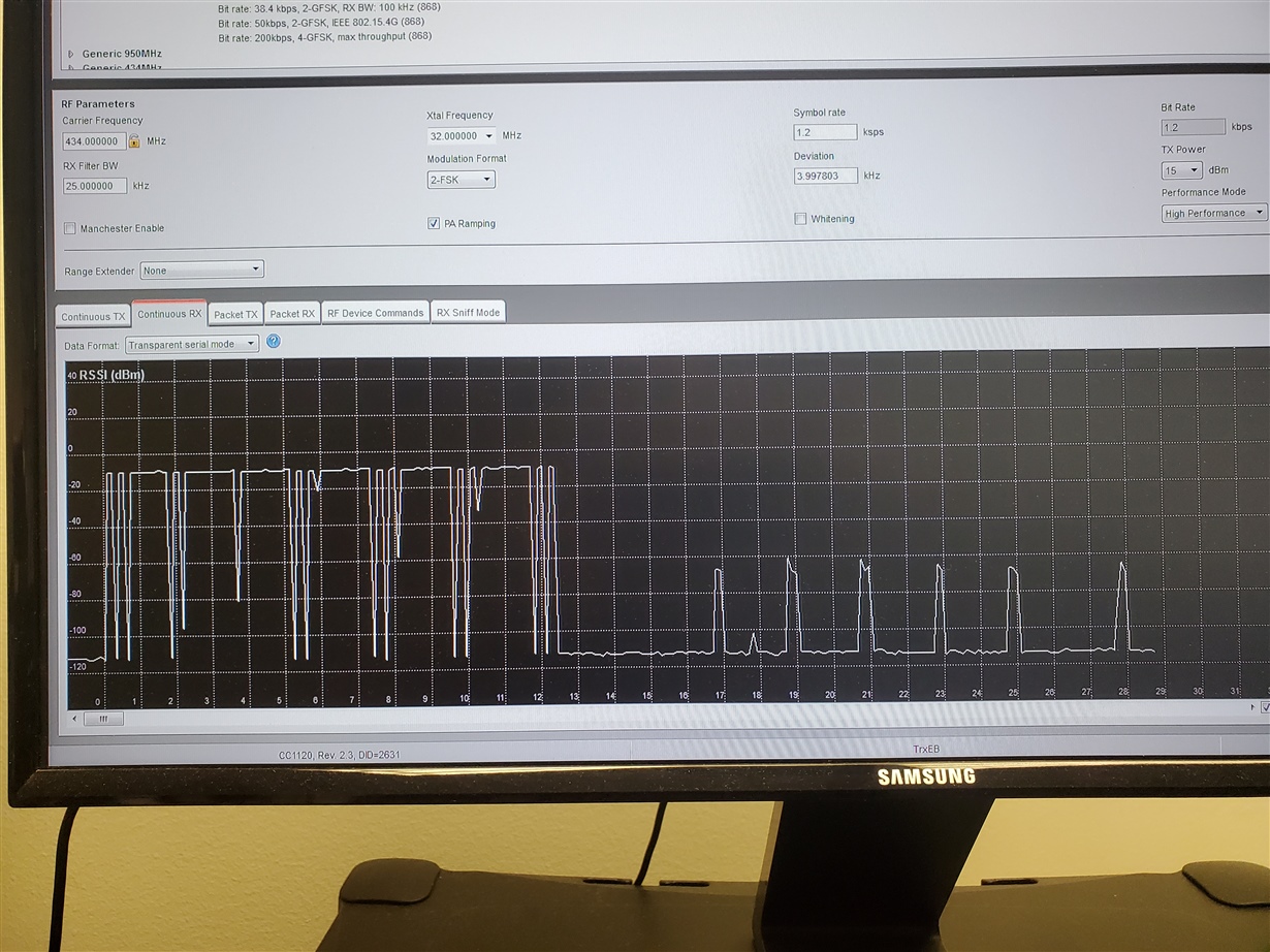
  • I put the RX demo in Continuous RX mode with the TX demo.  See first tall plots.  Worked fine.  The much lower plots are from my custom TX.  No packets received.  Why would those plots be so small so that they are not received as packets?  The are received as packets on my custom RX board.  Is there an amplifier on the demo board?

  • From what you are describing, it is obvious that you have a problem with your HW. When you do not get a sync signal on the RX side, that means that the demo board is not able to demodulate any of your data.

    It could for example be that your custom board has a frequency offset compared to the demo boards. In that case, you might be able to communicate between two custom boards, given that they have the same offset, but not between a custom board and a demo board/LP.

    You might also have problems using sniff mode when using your demo boards, if you are sending with poor output power, since the receiver will only receive packets with a certain RSSI in sniff mode (not the case in ordinary RX mode).

    I will re-assign this case to our HW team so that someone there can help you further.

    BR

    Siri

  • Yeah.  Not sure at this point.  Could be a HW issue, but it was confirmed twice as looking good by your support team.  And, I checked again our schematic and it looks the same as the TI schematic.  Doesn't mean there is not a wrong part on the board, but we've looked that over too. 

    I just reconfirmed that my custom HW works together on Continuous Mode at about RSSI = -30.  And, our scope sees both SYNC pulses.  But, not with your demo board.  TX sends one, RX does not receive.

  • This post was unfortunately lost for some time in the system.

    I believe I have taken a look at your schematic but I can't remember if I did. Who look at your schematic last? I want to take a brief look at again with the context of this thread to see if I get some ideas.  

  • This is the schematic for both my RX and TX.  See if you see any mistakes/omissions.

    CC1120design2.pdf

  • The TX doesn't have any GPIO wakeup pins.  The RX does.  The last post was the TX.  This is the RX.0676.CC1120design2.pdf

  • I see that you have used smaller load caps on the xtal on your HW than I would have expected. If you haven't done so, program your custom HW to send a CW and check if the frequency is correct. 

  • Can you be more specific on which caps you are referring to?  Our schematic should match the TI schematic.  Are there some wrong values?

  • You are correct, the cap values are the same as in the reference design. That said, the parasitic cap on the xosc_q1 and xosc_q2 will be slightly different from layout to layout so my main point is still relevant: Do you have a frequency offset? 

  • No offset freq.  For now, we have tried to 'copy' the reference design and use the exact SmartRF values for a 434MHZ model to form a working RX/TX custom pair.  Nothing different.  That was what your support people told us was the best way to start this project.  That way, once we understand how the chip works, we may or may not make some slight changes.  As I have mentioned, we have 2 demo boards that work perfectly together with 434MHZ SmartRF settings (ContTX and ContRX).  Our custom boards work perfectly together with these settings as well.  But, the demo board and our custom boards do not work together.  So, there is something we are still missing.

    Not sure what "program your custom HW to send a 'CW' and check if the frequency is correct" means.

  • I do not see a 'SOFT_TX_DATA_CFG' register in the user manual or in the SmartRF register list for the CC1120 to enable CW.  Is this a special register?

  • Sorry, old post. If you search for this register in the UserGuide you will see that this has changed name to CFM_DATA_CFG

  • OK.  Got it.

  • So, I'm a little unsure how to set up my HW to generate a CW.  I can set up the demo board to operate as Continuous TX, set the freq to 434 MHZ, enable the CFG_DATA_EN bit and press START and it sends out a CW, which is received by a 2nd demo board and I have a spectrum analyzer that confirms 434MHZ.  So, in my SW, do I have do anything special, or does enabling just CFG_DATA_EN automatically start sending a CW?  I'm not sure what the demo board TX SW is doing (if anything) when sending out a CW.  If I just set up my hardware with Continuous TX values, except change to 434MHZ (FS_CFG = 0x14) and set CFM_DATA_CFG = 0x01, is that all I need to do?  And then just go into an infinite loop?  And a CW will be sent out indefinitely?  Just trying to understand how it works.  Thanks.

  • After setting up the required registers you only have to issue a STX. 

  • OK.  I got my custom TX board to send a CW.  Both the demo board and my custom TX board are sending at 434MHZ - confirmed by my spectrum analyzer.  However, the signal strength received by the demo RX board is significantly different.  When the 2 TI demo boards communicate (with a CW), the RSSI is about -10 to -15dB.  When my custom TX board sends a CW, the demo RX receives a -70dB signal.  Not sure why the huge difference, since the schematics are the same.  Maybe the demo RX ignores signals that are that low, but my custom RX doesn't ignore it.

  • you need to measure the frequency with setting the RBW  =10 kHz (or less) to get the accuracy needed since you have to verify that your signal fit in the RX BW on the reciver.

    If you have a -70 dBm signal you have a significant HW issue, it sounds like you are missing one or more component, wrong setting etc.  

  • The settings are exactly the same as the Continuous TX settings in the SmartRF setup.  Except FS_CFG is 434MHZ, and CFG_DATA_CFG = 0x01.  No other changes.  Not sure what the problem is yet.  You have reviewed the schematic 3 times.

    OK.  So, change the RX Filter BW to 10KHZ (CHAN_BW to 0x14)?  SmartRF sets it to 0x08.

  • Sorry, typo. RBW on the spectrum to accurately measuring the frequency.

    Even if the schematic look ok you still can have assembly issues etc that cause HW issue.  

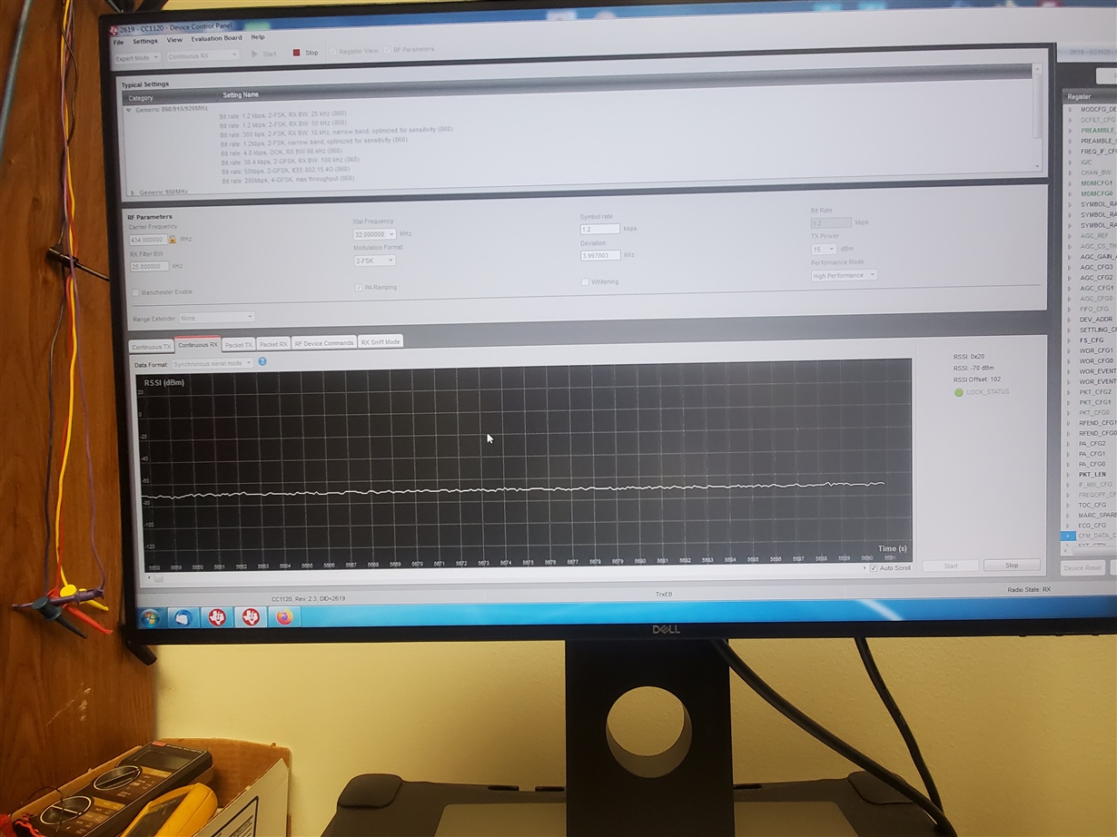
  • So, I set up my spectrum analyzer to RBX of 10Khz and the TX freq of both the TX demo board and my custom TX board still was 434MHZ on separate experiments.  My spectrum analyzer showed both RSSI at -18dB.  The RX demo also showed the TX demo at -18dB.  But, it showed my custom board at -70dB.  Why would the RX demo board show such a low RSSI, when my analyzer showed it at -18dB?

  • Could you post a screenshot of your measurements with a marker at peek?

  •   [quote user="TER"]

    Could you post a screenshot of your measurements with a marker at peek?

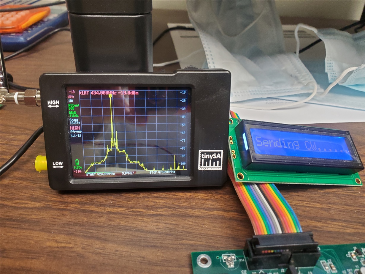
    The first picture is my SA (and custom TX board sending CW), which shows 434MHZ at RSSI -19dB.  The second is the SmartRF showing -70dB. 

  • Could you disclose the potential volume for this project? I suspect that to be able to solve this I need to look at the HW. 

  • Hard to tell.  We manufacture security equipment for the US federal govt. and we get requests to develop specific types of systems that do a specific task.  The govt. doesn't release any buying information until the prototype works and they like it.  They have asked us to develop system that has a RX/TX component that they can use for specific security operations.  So, we are doing that.  We went with the TI chip, because it looked easy to use - but we have several others we have looked at as well.  I'm hoping we can get this figured out, as the overall project is slated to be presented at the end of summer.

  • Is this CC1120 chip abundantly used?  I only get forum responses from you and one other person to questions.  Usually with forums, you get a lot of users responding with suggestions.  I'm not used to only getting responses from 2 people.  Therefore, I'm a little concerned that this chip is not widely used.

  • One more piece of information.  If I make both TI demo boards Continuous RX, and my custom TX board sending a CW, the RSSI on one RX is -70dB, and the other is -85dB.  My SA is still -18dB.  Maybe I have bad demo boards.  Or not calibrated very well.  I have not tried setting up my custom RX to receive a CW yet to see what it reads for RSSI.

  • CC1120 is widely used but the team handling the forum is small and hence you will not see a lot of different people answering questions. 

    The schematic I have seen show only the CC1120 part. Is it easy to connect a CCDebugger or a TRXEB to the SPI interface if I chose to look at it in the lab? 

  • Yes.  I can hook up a TRXEB board to my custom board fairly easily.  I have a SPI debug header for that exact scenario.  I can try that and see what the data shows.  Hadn't thought of that.

    On a side note, I was trying to configure my custom RX to receive a CW from my TX and be able to print out RSSI data to my display and see what that shows.  With loading of the Continuous RX registers (SmartRF) and changing FS_CFG to 434MHZ, it's not working quite yet.  What is the RX procedure for that?  Just issue a RTX, and start reading RSSI?  There is an interrupt of 0x08 for GPIO2 (my GPIO0).  Is that needed as the interrupt source?

  • For a cont RX no interrupt source is needed.

    And it should be sufficient to export the register settings for 433 MHz and strobe SRX and then read out RSSI.

  • I got the Continuous RX working on my board.  It shows -22dB consistently with my TX sending a CW.  My SA shows -17dB.  The demo TRXEBs show -75dB and -70dB consistently.  Not sure why the big difference.

    With my Continuous RX working, I set the TRXEB board to Continuous TX at 434Mhz.  My RX board registers -85dB, while the other TRXEB shows -23dB.   There is obviously something not right.

  • Frequency offset. When you measured the exact frequency the board operated on you just measured on one board. If you do the same for both the custom board you use and the TRXEM board, what is the delta between these frequencies? 

  • 434MHZ                                               Custom Board Cont RX                          TRBEX Cont RX                               Spectrum Analyzer

    Custom Board TX CW                                     -25dB                                                    -70dB                                                    -17dB

    TRBEX Board TX CW                                        -85dB                                                    -20dB                                                    -30dB


    All devices are within 3 feet of each other.

  • The exact frequency both operate on, not dBm numbers. 

  • According to my SA, the TRXEB board is sending a CW at 434.008MHZ.  My custom TX board is sending at 434.012MHZ.  Consistently.   Is that what you are asking?

  • A delta of 4 kz should be fine. What happens if you adjust the frequency of your custom board a bit down so the board send on the same frequency as the other board? Check RSSI first since you should measure more than -70ish. 

  • Can you give a little guidance on changing the freq up or down?  Is that FREQOFF1 and FREQOFF0 adjustments?  Is there a writeup on how to do this?  I couldn't find it in the manual.

    I am also in the process of hooking my TX up to the TRXEB board and see if that performs differently.

  • Equation 26 and 27 in https://www.ti.com/lit/ug/swru295e/swru295e.pdf but the easiest is to use SmartRF Studio calculate it for you. 

  • OK.  Thanks.  I will play with those settings and see if I can get a good feel on how that offset works.  And, verify with my SA.

    I have 4 custom TX boards, 3 with radio chips, 1 without.  The 3 boards with chips work exactly the same.  That is, they all work together with my custom RX, with RSSI of about -20dB.  The SA also shows -20dB.  However, the TRXEB RX shows -70dB for all 3. 

    I connected the SPI header from my TX board without the RX chip to the TRXEB board on its SPI header and easily commanded the demo radio chip to send a CW.  Without any adjustments, the freq on my SA was slightly better at 434.000-434.003 consistently with a RSSI of -12dB on both the SA and the TRXEB RX board.  However, my custom RX board still shows -70dB.

    So, still the main issue I'm fighting is why the big RSSI difference across boards.  The TRXEB RX board doesn't like my TX signals, and my RX board doesn't like the TRXEB TX signals.  But, the SA shows all good at -20dB and my boards communicating together show -20dB and the TRBEX boards communicating together show -20dB.  But, the different boards don't communicate with each other, probably because of the big RSSI discrepancy.  Which is where this all started.

    I think you've done all you can to help, and I appreciate it.  I know it's hard to debug via email or forum posts sometimes.  We'll just have to figure it out.

  • OK.  A few things worthwhile that I figured out.  I discovered that if I set the demo RX at 20KHZ off freq, the dB is much better (my custom TX at 434.000 and the demo RX at 434.020).  So, a question is we have 0805 parts for the TX, so our techs can make modifications if we have to.  Your demo board has 0402 parts.  Is the tolerance vastly different between the 2 package sizes so that we have this type of freq shift?

    Also, if we have 10 TXs communicating with one RX, is it such that each TX must be 'tuned' to work with that RX and that swapping out to another RX with the same 10 TXs might require complete retuning of the TXs?

    Just a couple of questions after I saw that the freq shift of the demo RX provided vastly different dB results.

  • 0805 components for the RF path is strongly not recommended. Since the components are a lot bigger the routing is much longer meaning much larger parasitics. For the tolerance, you can check in the datasheet for the components you are using and the for the ones used in the ref design.