This thread has been locked.

If you have a related question, please click the "Ask a related question" button in the top right corner. The newly created question will be automatically linked to this question.

CC1101: Compatibility with obsolete FSK transmitter/receiver circuits

Part Number: CC1101

Hello,

One of my customers has an old UHF FSK telemetry product line, based on the ATA8403 transmitter IC with FSK through external XTAL pulling, and a ATA5761 receiver, both of which are rapidly becoming obsolete. I was asked if I could design a new TX/RX system, and I am considering the CC1101.

The question is if this device is suitable to build a system that is still compatible with the older system. I am basically a hardware designer with no real experience with these newer devices or with actual transmission schemes, and I can't really judge by the datasheet if I will run into problems or not -- which is why I would like the experts' opinion here before spending a lot of time on actually building and programming things.

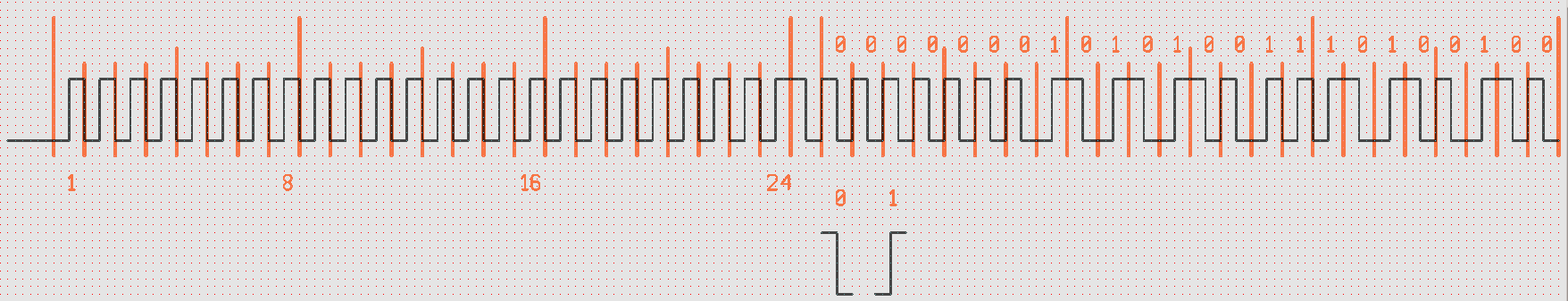
In the old ATA8403-based TX, a microcontroller simply shifts the crystal frequency by switching a parallel capacitor on and off. The primary carrier frequency is 869.2 MHz, with a modulation depth of ~25 kHz above primary. Each data frame consists of a 24-bit pre-burst (all ones), then a separator bit (0), followed by 24 or 32 data bits with the actual information, with a 1 kHz bit rate.

Is this something that the CC1101 can do? Or does it have certain limitations with regard to the actual data stream? The CC1101 datasheet mentions a burst mode with 64-byte FIFOs, so does that mean that the described data format with 49 or 56 bits in total should be no problem? And if so, what happens to that 24-bit pre-burst? I suppose that it is used to get the RX side to lock onto the signal, but that would mean that the first few bits might be lost.

Any thoughts are appreciated -- and also any links to more basic information on transmission formats at the hardware and software level, as I have little experience with this particular area of electronics (I haven't even figured out what particular type of FSK the above is, if any). I'm also still not certain if I should take on this job, or find someone with more experience.

Thanks already for any insights,

Richard

  • Do you need to be compatible to the old system? Will it be a disruption if you design a system that use a different packet format than what you have described?

    If you need to be compatible to the old system I believe that this should be possible with CC1101. I don't have experience with the ATA parts you listed above and I'm not sure based on the above how the signal looks on the air. Before starting it would most likely be a good idea to sniff the signal with a spectrum and verify the modulation format. Based on this I can try to point you to how you have to set up the chip. 

    The number of bytes in the packet is not a problem, CC1101 can handle any length. 

  • TER said:
    Will it be a disruption if you design a system that use a different packet format than what you have described?

    Well, yes, in that the end customers using existing products can't simply buy a few extra devices as they do now when the formats are not compatible. I might implement a new packet format for new systems anyway, but supporting the old format still represents a significant extra value to all parties.

    TER said:
    I'm not sure based on the above how the signal looks on the air

    The above shows one full transmission. Low level is 869.2 MHz, high level is shifted up by 25 kHz, so 869.225 MHz.

    Each full period = 1 bit = 1 ms, so there are 24 'pre-burst' bits (all 1), then one zero value (the separator), followed by three data bytes 0x0153A4 (I left out one optional byte).

    In total, there are 49 bits, and total duration is also 49 ms. The transmitter is switched on approximately 100 ms before the start of the pre-burst (not shown here), transmitting a 869.2 MHz carrier at that point. After the 49th bit, the transmitter is switched off within a few ms.

    If you think that this scheme should be no problem with the CC1101, I could make an offer to my customer, start building a few prototypes and really dive into the matter. The main purpose of my question here is to prevent spending money and time on building designs that are inherently unsuitable.

    Anyway, thank you already for your swift reply, and I hope you can confirm my hopes that the CC1101 is suitable for both transmitting and receiving the packet format shown here. A few pointers on how to accomplish this would of course be most welcome.

    Best regards,

    Richard

  • Thank you for the plot. It looks like the carrier on CC1101 should be set to 869.2125 MHz and the deviation to 12.5 kHz. The difference between +deviation and -deviation will therefore be 25 kHz. 

    For this it could be a good idea to get CC1101EMK868-915 + TRXEB and then you can use SmartRF Studio to start with for the basics (see that you actually receive and send a packet) and then when you have the basics in place, make a board with CC1101 + a MCU. 

  • TER said:
    For this it could be a good idea to get CC1101EMK868-915 + TRXEB and then you can use SmartRF Studio to start with for the basics

    Unfortunately, this is not an option, as there appears to be no Linux version of SmartRF Studio, nor are there any Linux APIs (I have Linux machines exclusively).

    But I should be able to sort things out using the datasheet and other resources. Your positive assessment is reassuring enough for me to go ahead and start building and experimenting with things. I have suitable equipment to check in detail what happens hardware-wise.

    Thanks again for your time, and if I should get seriously stuck at some point, I will no doubt return here and ask for some more help.

    Richard