This thread has been locked.

If you have a related question, please click the "Ask a related question" button in the top right corner. The newly created question will be automatically linked to this question.

CC1310 Partial Read RX Entry Questions

Other Parts Discussed in Thread: CC1310

The specifics of our wireless protocols require that we run CC1310 in the Proprietary Radio  mode of operation. 

All our  tests at the moment are done on SmartRf evaluation boards and mostly based on the rfPacketRx_CC1310DK_7XD_TI_CC1310F128 and rfPacketTx_CC1310DK_7XD_TI_CC1310F128 reference projects.


Receive mode.

We need to use the Partial Read RX Entry and we need to be able to stop reception once we determine that we reached the end of packet.  

Since we don’t  know the length of the received data until we get the END OF PACKET marker we use a receive data queue with data entries in a circular buffer like in the rfPacketsRx  reference design except we use Partial Read RX entries.

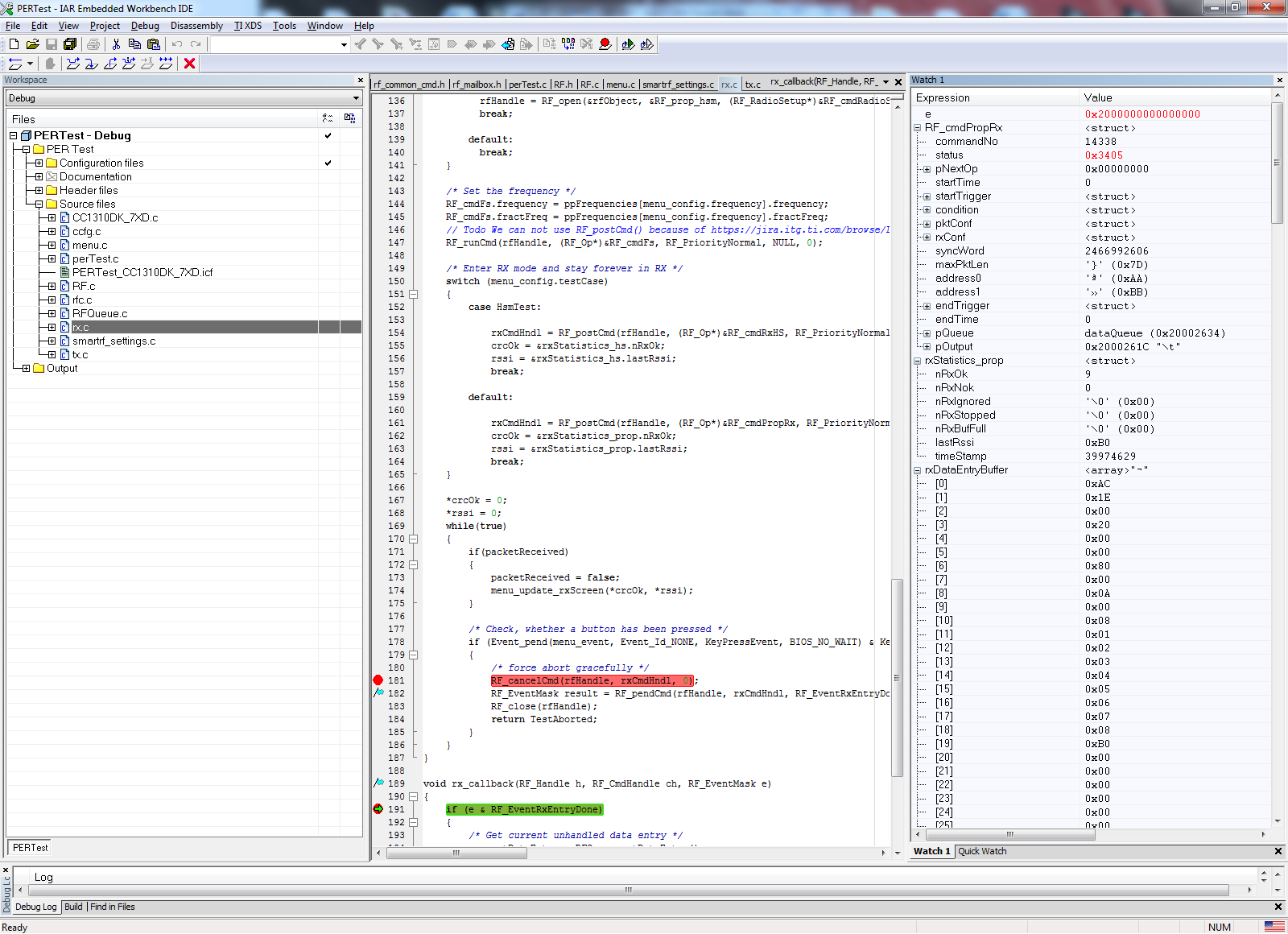
Once the reception is started the only viable way for us to stop it is by sending the CMD_ABORT.  We use the RF_cancelCmd with the “abrupt end” parameter.

Here is what we observed and need help understanding/using:


  1. When the RF_cancelCmd function is executed, the call back function is called with the zero value in the RF_EventMask e variable. It is not documented anywhere and we would like to know if it is an anomaly and if we can use it as an indicator to the callback function that the abort command was executed.  
  2. The Output structure is not updated when receive mode is terminated by either CMD_ABORT or CMD_STOP. This behaviour is not documented.  We would like to use this structure.   
  3. The RSSI value when requested by setting RF_cmdPropRx.rxConf.bAppendRssi = 0x1 is appended to the packet but is always set to 0x80.  Note that the time stamp is appended properly.  We need the RSSI.


I would like to add another question for the receive mode.


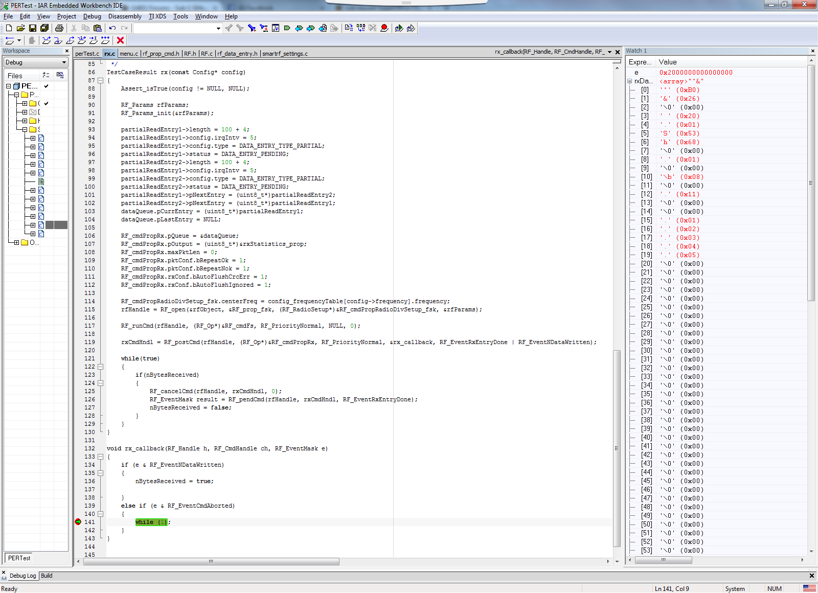
We found that the receiver generates call backs with the RF_EventRxEntryDone event at a rate that differs from what is actually received from the air by exactly one byte.

For example the size of each partial read entry in the receive queue is configured to be 11.  4 bytes of it are for the pktStatus and nextIndex fields, and the remaining 7 bytes are for user data.  We confirmed, by examining the nextIndex after reception,  that the radio puts exactly 7 bytes into each entry – nextIndex = 7.  

But the interrupts come at a rate as if 8 bytes are received from the air.

With the link rate of 50 kbps each byte should take 160us, and one complete data entry – 7 * 0.16 = 1.12ms.  In the actual test we see the ISR runs every 1.28ms, which translates to 8 bytes.   

Can you tell us what is happening? 

I should also add that as the entry size goes down, the interrupt behavior becomes pretty much chaotic.  I may see a gap of a millisecond, followed by three interrupts in a span of 40 microseconds.   Eventually the system hangs at a random time.

 It is very important for us to use short entries, because we need to have low latency between the actual end of a packet and the moment we detect it.  

Thanks!

  • Hi

    I am not able to reproduce or explain what you are observing.

    I have some test code that where I cancel RX with the RF_cancelCmd. I then get into my callback and e = 0x2000000000000000, which corresponds to RF_EventCmdAborted.

    Not sure what you mean by not updated. The RF core will not reset the output structure after an abort. This must be done from the application.

    In my test code, the appended RSSI is equal to the RSSI in the output structure, as you can see in the screenshot below (rxDataEntryBuffer[19] = lastRssi).

    I will send you my code so that you can take a look at it.

    To be able to answer your questions when it comes to timing, it would be useful if you could send us some code that we can run and also a setup as to how you are measuring.

    BR

    Siri

  • Hi Siri,

    The original question was about Partial Read Entry.  Your example uses DATA_ENTRY_TYPE_GEN.  Is it possible for you to verify the Partial Read Entry operation?

    The Output structure not "updated" means that the CC1310 was supposed to write into this structure when it finishes reception.  In case of Partial Read Entry, CC1310 does not write anything to the structure.

    Time is measured by a oscilloscope or a logic analyser with an LED toggle inside the callback.    

    Yes, we can send you a complete project along with scope captures.

    Thanks,

    Sergey

  • I am sorry for the late reply. I wrote an answer to this post several days ago but it seems like I did not manage to post it.

    The original question was about the RF_cancelCmd function and the RF_EventMask mask and this is why I sent you the code that I sent.

    The behavior of these commands are not in any way related to what type of data entry you are using, so I simply sent you a code example that I had available to show you how the abort commands works.

    When it comes to the output structure, this is also updated in the same way both when using partial read entries and “normal” data entries. The reason that you are not seeing them being updated is because you are exiting RX mode by using an abort command instead of letting RX mode terminate automatically. The structure contains info about the packets received. The way you use the radio, the radio core has no knowledge on what a packet is since it has no length info, and it can therefore not report CRC info and info regarding a packet the way it can when it terminates RX when a certain numbers are received (based on fixed or variable length mode).

    If your length information is somewhere in the packet not being supported by the standard packet format you will use infinite packet length mode and a partial read entry. You will then set up an interrupt when x numbers of bytes are received to be sure that you have received the length information. When this info is received you will use the CMD_PROP_SET_LEN command to let the RF core get the length information. When all bytes are received, a packet is received, and the radio will exit RX mode and update the structure.

    The code below shows an example using a partial read entry where the length byte is the 5th byte after the sync word.

    static void rxTaskFunction(UArg arg0, UArg arg1)
    {
        RF_Params rfParams;
        RF_Params_init(&rfParams);
    
        partialReadEntry1->length = 100;
        partialReadEntry1->config.type = DATA_ENTRY_TYPE_PARTIAL;
        partialReadEntry1-> config.lenSz  = 5;
        partialReadEntry1->status = DATA_ENTRY_PENDING;
    
        partialReadEntry1->pNextEntry = (uint8_t*)partialReadEntry1;
    
        dataQueue.pCurrEntry = (uint8_t*)partialReadEntry1;
        dataQueue.pLastEntry = NULL;
        
        /* 4.1. Modify CMD_PROP_RX command for application needs */
        RF_cmdPropRx.pQueue = &dataQueue;               /* Set the Data Entity queue for received data */
        RF_cmdPropRx.maxPktLen = 0;                     /* Unlimited length */
        RF_cmdPropRx.rxConf.bAutoFlushCrcErr = 0x0;     /* Auto-flush packets with invalid CRC */
        RF_cmdPropRx.pktConf.bRepeatNok = 0x0;          /* Exit RX after a packet is recived */
        RF_cmdPropRx.pktConf.bRepeatOk = 0x0;           /* Exit RX after a packet is recived */
        RF_cmdPropRx.pOutput = (uint8_t*)&rxStatistics;
    
        /* Request access to the radio */
        rfHandle = RF_open(&rfObject, &RF_prop, (RF_RadioSetup*)&RF_cmdPropRadioDivSetup, &rfParams);
        
        /* Set the frequency */
        RF_postCmd(rfHandle, (RF_Op*)&RF_cmdFs, RF_PriorityNormal, NULL, 0);
        
        while(1)
        {
            RF_runCmd(rfHandle, (RF_Op*)&RF_cmdPropRx, RF_PriorityNormal, &callback, IRQ_RX_N_DATA_WRITTEN);
        }
      
    }
    
    void callback(RF_Handle h, RF_CmdHandle ch, RF_EventMask e)
    {
        if (e & RF_EventNDataWritten)
        {
            RF_cmdPropSetLen.rxLen = rxDataEntryBuffer1[DATA_ENTRY_HEADER_SIZE + 4] + 4;
            RF_runDirectCmd(rfHandle, (uint32_t)&RF_cmdPropSetLen);
        }
        else /* RF_EventCmdDone */
        {
            /* Toggle pin to indicate RX */
            PIN_setOutputValue(pinHandle, Board_LED2,!PIN_getOutputValue(Board_LED2));
            
            partialReadEntry1->status = DATA_ENTRY_PENDING;
        }
    }

    Siri

  • Hi Siri,

    I think I failed to communicate to you the specifics of our application and that is why I can't seem to get the answers that I am looking for. Also, I asked too many questions in one post. I will tackle them one by one.  

    We need to receive very big packets of varying size that can't be kept in the memory entirely.  The memory constraints are so tight that we MUST use a queue of circular data entries, like in RFQueue.c, except it is a partial read entry. The size of each entry is just 8 bytes:  4 bytes for header, 4 bytes for data from the air. We want to start reception, get IRQ_RX_ENTRY_DONE interrupts every 4 bytes received from the air, read data from the entry, send it for processing to a data task and reload the entry.  Once the data task decides that the message is over, the task must stop the reception.  The reception must be stopped as soon as possible after the moment the data task decides to stop it.

    This application usage mode is completely different from both of your examples that you supplied so far. Your example uses just one big (100 byte) entry and stops reception in the callback function while this entry is being processed.  We can't use one big entry. We need a circular buffer of short entries. Using the circular buffer of short data entries means that you can't simply set the length of the complete packet by using RF_cmdPropSetLen.  This command apparently sets the size of the entry being processed, not the size of the total payload. At least this is how we understand it given the absence of detailed explanation in the manual.

    Can you please clarify how to terminate the receive mode when a short queue of circular partial read data entries with a small size of 8 bytes each is used and the reception must be terminated at a later time, say after a total of 1200 bytes is received and the final size of the payload is determined to be 1216?

    thanks!

  • Ok. If you want to stop the reception by sending the abort command when you know the packet is done, this is perfectly OK. The only thing is that you will not have any info in the output struct and you need to calculate CRC manually. If you need the RSSI value, you can read this while in RX, by using the GET_RSSI command.

    The example I showed with the SET_LEN command can also be used even if you have a queue of several small data entries. The only challenge is if you length info is the last byte in the packet, that is, you have no length info but simply a byte that indicates that you now should not receive anything more. In theory, you could then set the length to the number of bytes you have already received, but since it takes some time to send the command, the radio will already have receive another byte, and the length info you are sending would be illegal.

    Not sure I understand on what format your length info is, but if you after receiving 1200 bytes get knowledge that there are 16 bytes left to receive, the length should be set to 1216.

    Siri

  • Thanks Siri, as I said in my original post, this is exactly what we are doing - sending the abort command to the radio when the data task determines that the packet is over. To clarify the length format info - we don't have one. The end of a packet is indicated by a specific data pattern - end_of_packet_marker.
    Now that you confirmed that using the Abort command is perfectly normal, I want to go back to my original post and my original questions.
    You answered one of them - the output structure is not updated when reception is aborted by the abort command. This is not documented in the Reference Manual but you clarified it. Thank you.

    Back to the first on my original questions:
    1. When the RF_cancelCmd function is executed, the call back function is called with the zero value in the RF_EventMask e variable. It is not documented anywhere and we would like to know if it is an anomaly and if we can use it as an indicator to the callback function that the abort command was executed.

    thanks!
    Sergey
  • Hi

    Unfortunately I am not able to reproduce what you are seeing. I now wrote a small example using partial read entries and the RF_EventNDataWritten interrupt (I get the interrupt when 5 bytes are received in the data entry). When I have received these bytes I send RF_cancelCmd.

    You can see below that I get the RF_EventCmdAborted interrupt and reception is stopped after 5 bytes (I am actually sending 1, 2, 3, 4, 5, 6, 7, 8, 9, a, b, c, d, e, f). The RF_EventMask e is 0x2000000000000000, as expected.

    Siri

  • Hi Sergey,
    In you forum you mentioned that you are sending more than 255 bytes of data and since the length of data sent/receive is unknown you are using the partial read entry concept.
    Now my concern for the project we are working on is how to send more than 255 bytes of data. I have tried using the TX_ADV and RX_ADV command but at the receiver end I am always getting CRC error. I haven't used the partial read entry as we are aware we want to transmit and receive 512 bytes of data every time.
    Please provide some suggestion.
    Vikram
  • Hi

    I have taken the rfPacketRX and rfPacketTx example and modified it to send packets longer than 255 bytes and to use the advanced RX andTX commands.

    Hope that helps.

    8547.smartrf_settings.c
    
    //*********************************************************************************
    // These settings have been generated for use with TI-RTOS and cc13xxware
    //
    // Generated by SmartRF Studio version 2.4.3 (build #23)
    // Tested for TI-RTOS version tirtos_simplelink_2_18_00
    // Device: CC1310 Rev. 2.1
    // 
    //*********************************************************************************
    
    
    //*********************************************************************************
    // Parameter summary
    // Address: aa-bb 
    // Frequency: 868.00000 MHz
    // Data Format: Serial mode disable 
    // Deviation: 25.000 kHz
    // Packet Length Config: Variable 
    // Max Packet Length: 125 
    // Packet Length: 30 
    // RX Filter BW: 98 kHz
    // Symbol Rate: 50.00000 kBaud
    // Sync Word Length: 32 Bits 
    // TX Power: 14 dBm (requires define CCFG_FORCE_VDDR_HH = 1 in ccfg.c, see CC13xx/CC26xx Technical Reference Manual)
    // Whitening: No whitening 
    
    #include <driverlib/rf_mailbox.h>
    #include <driverlib/rf_common_cmd.h>
    #include <driverlib/rf_prop_cmd.h>
    #include <ti/drivers/rf/RF.h>
    #include <rf_patches/rf_patch_cpe_genfsk.h>
    #include <rf_patches/rf_patch_rfe_genfsk.h>
    #include "smartrf_settings.h"
    
    
    // TI-RTOS RF Mode Object
    RF_Mode RF_prop =
    {
        .rfMode = RF_MODE_PROPRIETARY_SUB_1,
        .cpePatchFxn = &rf_patch_cpe_genfsk,
        .mcePatchFxn = 0,
        .rfePatchFxn = &rf_patch_rfe_genfsk,
    };
    
    // Overrides for CMD_PROP_RADIO_DIV_SETUP
    static uint32_t pOverrides[] =
    {
        // override_use_patch_prop_genfsk.xml
        // PHY: Use MCE ROM bank 4, RFE RAM patch
        MCE_RFE_OVERRIDE(0,4,0,1,0,0),
        // override_synth_prop_863_930_div5.xml
        // Synth: Set recommended RTRIM to 7
        HW_REG_OVERRIDE(0x4038,0x0037),
        // Synth: Set Fref to 4 MHz
        (uint32_t)0x000684A3,
        // Synth: Configure fine calibration setting
        HW_REG_OVERRIDE(0x4020,0x7F00),
        // Synth: Configure fine calibration setting
        HW_REG_OVERRIDE(0x4064,0x0040),
        // Synth: Configure fine calibration setting
        (uint32_t)0xB1070503,
        // Synth: Configure fine calibration setting
        (uint32_t)0x05330523,
        // Synth: Set loop bandwidth after lock to 20 kHz
        (uint32_t)0x0A480583,
        // Synth: Set loop bandwidth after lock to 20 kHz
        (uint32_t)0x7AB80603,
        // Synth: Configure VCO LDO (in ADI1, set VCOLDOCFG=0x9F to use voltage input reference)
        ADI_REG_OVERRIDE(1,4,0x9F),
        // Synth: Configure synth LDO (in ADI1, set SLDOCTL0.COMP_CAP=1)
        ADI_HALFREG_OVERRIDE(1,7,0x4,0x4),
        // Synth: Use 24 MHz XOSC as synth clock, enable extra PLL filtering
        (uint32_t)0x02010403,
        // Synth: Configure extra PLL filtering
        (uint32_t)0x00108463,
        // Synth: Increase synth programming timeout (0x04B0 RAT ticks = 300 us)
        (uint32_t)0x04B00243,
        // override_phy_rx_aaf_bw_0xd.xml
        // Rx: Set anti-aliasing filter bandwidth to 0xD (in ADI0, set IFAMPCTL3[7:4]=0xD)
        ADI_HALFREG_OVERRIDE(0,61,0xF,0xD),
        // override_phy_gfsk_rx.xml
        // Rx: Set LNA bias current trim offset to 3
        (uint32_t)0x00038883,
        // Rx: Freeze RSSI on sync found event
        HW_REG_OVERRIDE(0x6084,0x35F1),
        // override_phy_gfsk_pa_ramp_agc_reflevel_0x1a.xml
        // Tx: Enable PA ramping (0x41). Rx: Set AGC reference level to 0x1A.
        HW_REG_OVERRIDE(0x6088,0x411A),
        // Tx: Configure PA ramping setting
        HW_REG_OVERRIDE(0x608C,0x8213),
        // override_phy_rx_rssi_offset_5db.xml
        // Rx: Set RSSI offset to adjust reported RSSI by +5 dB
        (uint32_t)0x00FB88A3,
        // TX power override
        // Tx: Set PA trim to max (in ADI0, set PACTL0=0xF8)
        ADI_REG_OVERRIDE(0,12,0xF8),
        (uint32_t)0xFFFFFFFF,
    };
    
    
    // CMD_PROP_RADIO_DIV_SETUP
    rfc_CMD_PROP_RADIO_DIV_SETUP_t RF_cmdPropRadioDivSetup =
    {
        .commandNo = 0x3807,
        .status = 0x0000,
        .pNextOp = 0, // INSERT APPLICABLE POINTER: (uint8_t*)&xxx
        .startTime = 0x00000000,
        .startTrigger.triggerType = 0x0,
        .startTrigger.bEnaCmd = 0x0,
        .startTrigger.triggerNo = 0x0,
        .startTrigger.pastTrig = 0x0,
        .condition.rule = 0x1,
        .condition.nSkip = 0x0,
        .modulation.modType = 0x1,
        .modulation.deviation = 0x64,
        .symbolRate.preScale = 0xF,
        .symbolRate.rateWord = 0x8000,
        .rxBw = 0x24,
        .preamConf.nPreamBytes = 0x4,
        .preamConf.preamMode = 0x0,
        .formatConf.nSwBits = 0x20,
        .formatConf.bBitReversal = 0x0,
        .formatConf.bMsbFirst = 0x1,
        .formatConf.fecMode = 0x0,
        .formatConf.whitenMode = 0x0,
        .config.frontEndMode = 0x0,
        .config.biasMode = 0x1,
        .config.analogCfgMode = 0x0,
        .config.bNoFsPowerUp = 0x0,
        .txPower = 0xA73F,
        .pRegOverride = pOverrides,
        .centerFreq = 0x0364,
        .intFreq = 0x8000,
        .loDivider = 0x05,
    };
    
    // CMD_FS
    rfc_CMD_FS_t RF_cmdFs =
    {
        .commandNo = 0x0803,
        .status = 0x0000,
        .pNextOp = 0, // INSERT APPLICABLE POINTER: (uint8_t*)&xxx
        .startTime = 0x00000000,
        .startTrigger.triggerType = 0x0,
        .startTrigger.bEnaCmd = 0x0,
        .startTrigger.triggerNo = 0x0,
        .startTrigger.pastTrig = 0x0,
        .condition.rule = 0x1,
        .condition.nSkip = 0x0,
        .frequency = 0x0364,
        .fractFreq = 0x0000,
        .synthConf.bTxMode = 0x0,
        .synthConf.refFreq = 0x0,
        .__dummy0 = 0x00,
        .__dummy1 = 0x00,
        .__dummy2 = 0x00,
        .__dummy3 = 0x0000,
    };
    
    // CMD_PROP_TX_ADV
    rfc_CMD_PROP_TX_ADV_t RF_cmdPropTxAdv =
    {
        .commandNo = 0x3803,
        .status = 0x0000,
        .pNextOp = 0, // INSERT APPLICABLE POINTER: (uint8_t*)&xxx
        .startTime = 0x00000000,
        .startTrigger.triggerType = 0x0,
        .startTrigger.bEnaCmd = 0x0,
        .startTrigger.triggerNo = 0x0,
        .startTrigger.pastTrig = 0x0,
        .condition.rule = 0x1,
        .condition.nSkip = 0x0,
        .pktConf.bFsOff = 0x0,
        .pktConf.bUseCrc = 0x1,
        .pktConf.bCrcIncSw = 0x0,
        .pktConf.bCrcIncHdr = 0x0,
        .numHdrBits = 16,
        .pktLen = 0x0000,
        .startConf.bExtTxTrig = 0x0,
        .startConf.inputMode = 0x0,
        .startConf.source = 0x0,
        .preTrigger.triggerType = 0x0,
        .preTrigger.bEnaCmd = 0x0,
        .preTrigger.triggerNo = 0x0,
        .preTrigger.pastTrig = 0x0,
        .preTime = 0x00000000,
        .syncWord = 0x930B51DE,
        .pPkt = 0, // INSERT APPLICABLE POINTER: (uint8_t*)&xxx
    };
    
    // CMD_PROP_RX_ADV
    rfc_CMD_PROP_RX_ADV_t RF_cmdPropRxAdv =
    {
        .commandNo = 0x3804,
        .status = 0x0000,
        .pNextOp = 0, // INSERT APPLICABLE POINTER: (uint8_t*)&xxx
        .startTime = 0x00000000,
        .startTrigger.triggerType = 0x0,
        .startTrigger.bEnaCmd = 0x0,
        .startTrigger.triggerNo = 0x0,
        .startTrigger.pastTrig = 0x0,
        .condition.rule = 0x1,
        .condition.nSkip = 0x0,
        .pktConf.bFsOff = 0x0,
        .pktConf.bRepeatOk = 0x0,
        .pktConf.bRepeatNok = 0x0,
        .pktConf.bUseCrc = 0x1,
        .pktConf.bCrcIncSw = 0x0,
        .pktConf.bCrcIncHdr = 0x0,
        .pktConf.endType = 0x0,
        .pktConf.filterOp = 0x0,
        .rxConf.bAutoFlushIgnored = 0x0,
        .rxConf.bAutoFlushCrcErr = 0x0,
        .rxConf.bIncludeHdr = 0x1,
        .rxConf.bIncludeCrc = 0x0,
        .rxConf.bAppendRssi = 0x0,
        .rxConf.bAppendTimestamp = 0x0,
        .rxConf.bAppendStatus = 0x1,
        .syncWord0 = 0x930B51DE,
        .syncWord1 = 0x00000000,
        .maxPktLen = 0x0000,
        .hdrConf.numHdrBits = 16,
        .hdrConf.lenPos = 0x0,
        .hdrConf.numLenBits = 16,
        .addrConf.addrType = 0x0,
        .addrConf.addrSize = 0x0,
        .addrConf.addrPos = 0x0,
        .addrConf.numAddr = 0x0,
        .lenOffset = 0x00,
        .endTrigger.triggerType = 0x1,
        .endTrigger.bEnaCmd = 0x0,
        .endTrigger.triggerNo = 0x0,
        .endTrigger.pastTrig = 0x0,
        .endTime = 0x00000000,
        .pAddr = 0, // INSERT APPLICABLE POINTER: (uint8_t*)&xxx
        .pQueue = 0, // INSERT APPLICABLE POINTER: (dataQueue_t*)&xxx
        .pOutput = 0, // INSERT APPLICABLE POINTER: (uint8_t*)&xxx
    };


    rfPacketTx.c
    /*
     * Copyright (c) 2019, Texas Instruments Incorporated
     * All rights reserved.
     *
     * Redistribution and use in source and binary forms, with or without
     * modification, are permitted provided that the following conditions
     * are met:
     *
     * *  Redistributions of source code must retain the above copyright
     *    notice, this list of conditions and the following disclaimer.
     *
     * *  Redistributions in binary form must reproduce the above copyright
     *    notice, this list of conditions and the following disclaimer in the
     *    documentation and/or other materials provided with the distribution.
     *
     * *  Neither the name of Texas Instruments Incorporated nor the names of
     *    its contributors may be used to endorse or promote products derived
     *    from this software without specific prior written permission.
     *
     * THIS SOFTWARE IS PROVIDED BY THE COPYRIGHT HOLDERS AND CONTRIBUTORS "AS IS"
     * AND ANY EXPRESS OR IMPLIED WARRANTIES, INCLUDING, BUT NOT LIMITED TO,
     * THE IMPLIED WARRANTIES OF MERCHANTABILITY AND FITNESS FOR A PARTICULAR
     * PURPOSE ARE DISCLAIMED. IN NO EVENT SHALL THE COPYRIGHT OWNER OR
     * CONTRIBUTORS BE LIABLE FOR ANY DIRECT, INDIRECT, INCIDENTAL, SPECIAL,
     * EXEMPLARY, OR CONSEQUENTIAL DAMAGES (INCLUDING, BUT NOT LIMITED TO,
     * PROCUREMENT OF SUBSTITUTE GOODS OR SERVICES; LOSS OF USE, DATA, OR PROFITS;
     * OR BUSINESS INTERRUPTION) HOWEVER CAUSED AND ON ANY THEORY OF LIABILITY,
     * WHETHER IN CONTRACT, STRICT LIABILITY, OR TORT (INCLUDING NEGLIGENCE OR
     * OTHERWISE) ARISING IN ANY WAY OUT OF THE USE OF THIS SOFTWARE,
     * EVEN IF ADVISED OF THE POSSIBILITY OF SUCH DAMAGE.
     */
    
    /***** Includes *****/
    /* Standard C Libraries */
    #include <stdlib.h>
    #include <unistd.h>
    
    /* TI Drivers */
    #include <ti/drivers/rf/RF.h>
    #include <ti/drivers/PIN.h>
    //#include <ti/drivers/pin/PINCC26XX.h>
    
    /* Driverlib Header files */
    #include DeviceFamily_constructPath(driverlib/rf_prop_mailbox.h)
    
    /* Board Header files */
    #include "Board.h"
    #include "smartrf_settings/smartrf_settings.h"
    
    #include "RFQueue.h"


    /***** Defines *****/
    
    /* Packet TX Configuration */
    #define PAYLOAD_LENGTH          300
    #define DATA_ENTRY_HEADER_SIZE  8               // Constant header size of a Generic Data Entry
    #define MAX_LENGTH              PAYLOAD_LENGTH  // Set the length of the data entry
    #define NUM_DATA_ENTRIES_TX     1
    #define NUM_APPENDED_BYTES_TX   0
    #define NUMBER_OF_PACKETS       5
    
    /***** Prototypes *****/
    
    /***** Variable declarations *****/
    static RF_Object rfObject;
    static RF_Handle rfHandle;
    
    /* Pin driver handle */
    static PIN_Handle ledPinHandle;
    static PIN_State ledPinState;
    
    static uint8_t *pPacket;
    
    #if defined(__TI_COMPILER_VERSION__)
    #pragma DATA_ALIGN (txDataEntryBuffer, 4);
    static uint8_t
    txDataEntryBuffer[RF_QUEUE_DATA_ENTRY_BUFFER_SIZE(NUM_DATA_ENTRIES_TX,
                                                      MAX_LENGTH,
                                                      NUM_APPENDED_BYTES_TX)];
    #elif defined(__IAR_SYSTEMS_ICC__)
    #pragma data_alignment = 4
    static uint8_t
    txDataEntryBuffer[RF_QUEUE_DATA_ENTRY_BUFFER_SIZE(NUM_DATA_ENTRIES_TX,
                                                      MAX_LENGTH,
                                                      NUM_APPENDED_BYTES_TX)];
    #elif defined(__GNUC__)
    static uint8_t
    txDataEntryBuffer[RF_QUEUE_DATA_ENTRY_BUFFER_SIZE(NUM_DATA_ENTRIES_TX,
                                                      MAX_LENGTH,
                                                      NUM_APPENDED_BYTES_TX)]
                                                      __attribute__((aligned(4)));
    #else
    #error This compiler is not supported.
    #endif
    
    static dataQueue_t dataQueue;
    static rfc_dataEntryGeneral_t* currentDataEntry;
    static uint16_t packetCounter = 0;
    
    /*
     * Application LED pin configuration table:
     *   - All LEDs board LEDs are off.
     */
    PIN_Config pinTable[] =
    {
        Board_PIN_LED1 | PIN_GPIO_OUTPUT_EN | PIN_GPIO_LOW | PIN_PUSHPULL | PIN_DRVSTR_MAX,
        PIN_TERMINATE
    };
    
    /***** Function definitions *****/
    
    void *mainThread(void *arg0)
    {
        RF_Params rfParams;
        RF_Params_init(&rfParams);
    
        /* Open LED pins */
        ledPinHandle = PIN_open(&ledPinState, pinTable);
        if (ledPinHandle == NULL)
        {
            while(1);
        }
    
        if( RFQueue_defineQueue(&dataQueue,
                                    txDataEntryBuffer,
                                    sizeof(txDataEntryBuffer),
                                    NUM_DATA_ENTRIES_TX,
                                    MAX_LENGTH + NUM_APPENDED_BYTES_TX))
        {
            /* Failed to allocate space for all data entries */
            while(true);
        }
    
        RF_cmdTxHS.pQueue = &dataQueue;
        RF_cmdTxHS.startTrigger.triggerType = TRIG_NOW;
    
        currentDataEntry = (rfc_dataEntryGeneral_t*)&txDataEntryBuffer;
        currentDataEntry->length = PAYLOAD_LENGTH;
        pPacket = &currentDataEntry->data;
    
        /* Generate the packet */
        uint16_t i;
        for (i = 1; i < PAYLOAD_LENGTH; i++)
        {
            pPacket[i] = (uint8_t)(i - 1);
        }
    
        /* Request access to the radio */
        rfHandle = RF_open(&rfObject, &RF_prop, (RF_RadioSetup*)&RF_cmdRadioSetup, &rfParams);
    
        /* Set the frequency */
        RF_postCmd(rfHandle, (RF_Op*)&RF_cmdFs, RF_PriorityNormal, NULL, 0);
    
        while(1)
        {
            while(packetCounter++ < NUMBER_OF_PACKETS)
            {
                pPacket[0] = packetCounter;
                PIN_setOutputValue(ledPinHandle, Board_PIN_LED1,1);
                RF_runCmd(rfHandle, (RF_Op*)&RF_cmdTxHS, RF_PriorityNormal, NULL, 0);
                PIN_setOutputValue(ledPinHandle, Board_PIN_LED1,0);
            }
            usleep(500000);
            packetCounter = 0;
        }
    }
    

    6076.rfPacketRx.c
    /*
     * Copyright (c) 2015-2016, Texas Instruments Incorporated
     * All rights reserved.
     *
     * Redistribution and use in source and binary forms, with or without
     * modification, are permitted provided that the following conditions
     * are met:
     *
     * *  Redistributions of source code must retain the above copyright
     *    notice, this list of conditions and the following disclaimer.
     *
     * *  Redistributions in binary form must reproduce the above copyright
     *    notice, this list of conditions and the following disclaimer in the
     *    documentation and/or other materials provided with the distribution.
     *
     * *  Neither the name of Texas Instruments Incorporated nor the names of
     *    its contributors may be used to endorse or promote products derived
     *    from this software without specific prior written permission.
     *
     * THIS SOFTWARE IS PROVIDED BY THE COPYRIGHT HOLDERS AND CONTRIBUTORS "AS IS"
     * AND ANY EXPRESS OR IMPLIED WARRANTIES, INCLUDING, BUT NOT LIMITED TO,
     * THE IMPLIED WARRANTIES OF MERCHANTABILITY AND FITNESS FOR A PARTICULAR
     * PURPOSE ARE DISCLAIMED. IN NO EVENT SHALL THE COPYRIGHT OWNER OR
     * CONTRIBUTORS BE LIABLE FOR ANY DIRECT, INDIRECT, INCIDENTAL, SPECIAL,
     * EXEMPLARY, OR CONSEQUENTIAL DAMAGES (INCLUDING, BUT NOT LIMITED TO,
     * PROCUREMENT OF SUBSTITUTE GOODS OR SERVICES; LOSS OF USE, DATA, OR PROFITS;
     * OR BUSINESS INTERRUPTION) HOWEVER CAUSED AND ON ANY THEORY OF LIABILITY,
     * WHETHER IN CONTRACT, STRICT LIABILITY, OR TORT (INCLUDING NEGLIGENCE OR
     * OTHERWISE) ARISING IN ANY WAY OUT OF THE USE OF THIS SOFTWARE,
     * EVEN IF ADVISED OF THE POSSIBILITY OF SUCH DAMAGE.
     */
    
    /***** Includes *****/
    #include <stdlib.h>
    #include <xdc/std.h>
    #include <xdc/cfg/global.h>
    #include <xdc/runtime/System.h>
    
    #include <ti/sysbios/BIOS.h>
    #include <ti/sysbios/knl/Task.h>
    
    /* Drivers */
    #include <ti/drivers/rf/RF.h>
    #include <ti/drivers/PIN.h>
    #include <driverlib/rf_prop_mailbox.h>
    
    /* Board Header files */
    #include "Board.h"
    
    #include "RFQueue.h"
    #include "smartrf_settings/smartrf_settings.h"
    
    #include <stdlib.h>
    
    /* Pin driver handle */
    static PIN_Handle ledPinHandle;
    static PIN_State ledPinState;
    
    /*
     * Application LED pin configuration table:
     *   - All LEDs board LEDs are off.
     */
    PIN_Config pinTable[] =
    {
        Board_LED2 | PIN_GPIO_OUTPUT_EN | PIN_GPIO_LOW | PIN_PUSHPULL | PIN_DRVSTR_MAX,
        PIN_TERMINATE
    };
    
    
    /***** Defines *****/
    #define RX_TASK_STACK_SIZE 1024
    #define RX_TASK_PRIORITY   2
    
    /* Packet RX Configuration */
    #define DATA_ENTRY_HEADER_SIZE 8   /* Constant header size of a Generic Data Entry */
    #define MAX_LENGTH             350 /* Max length byte the radio will accept */
    #define NUM_DATA_ENTRIES       2   /* NOTE: Only two data entries supported at the moment */
    #define NUM_APPENDED_BYTES     3   /* The Data Entries data field will contain:
                                        * 2 Header byte (RF_cmdPropRxAdv.rxConf.bIncludeHdr = 0x1)
                                        * Max 350 payload bytes
                                        * 1 status byte (RF_cmdPropRxAdv.rxConf.bAppendStatus = 0x1) */


    /***** Prototypes *****/
    static void rxTaskFunction(UArg arg0, UArg arg1);
    static void callback(RF_Handle h, RF_CmdHandle ch, RF_EventMask e);
    
    /***** Variable declarations *****/
    static Task_Params rxTaskParams;
    Task_Struct rxTask;    /* not static so you can see in ROV */
    static uint8_t rxTaskStack[RX_TASK_STACK_SIZE];
    
    static RF_Object rfObject;
    static RF_Handle rfHandle;
    
    /* Buffer which contains all Data Entries for receiving data.
     * Pragmas are needed to make sure this buffer is 4 byte aligned (requirement from the RF Core) */
    #if defined(__TI_COMPILER_VERSION__)
        #pragma DATA_ALIGN (rxDataEntryBuffer, 4);
            static uint8_t rxDataEntryBuffer[RF_QUEUE_DATA_ENTRY_BUFFER_SIZE(NUM_DATA_ENTRIES,
                                                                     MAX_LENGTH,
                                                                     NUM_APPENDED_BYTES)];
    #elif defined(__IAR_SYSTEMS_ICC__)
        #pragma data_alignment = 4
            static uint8_t rxDataEntryBuffer[RF_QUEUE_DATA_ENTRY_BUFFER_SIZE(NUM_DATA_ENTRIES,
                                                                     MAX_LENGTH,
                                                                     NUM_APPENDED_BYTES)];
    #elif defined(__GNUC__)
            static uint8_t rxDataEntryBuffer [RF_QUEUE_DATA_ENTRY_BUFFER_SIZE(NUM_DATA_ENTRIES,
                MAX_LENGTH, NUM_APPENDED_BYTES)] __attribute__ ((aligned (4)));
    #else
        #error This compiler is not supported.
    #endif
    
    /* Receive dataQueue for RF Core to fill in data */
    static dataQueue_t dataQueue;
    static rfc_dataEntryGeneral_t* currentDataEntry;
    static uint16_t packetLength;
    static uint8_t* packetDataPointer;
    static rfc_propRxOutput_t rxStatistics;
    
    static PIN_Handle pinHandle;
    
    static uint8_t packet[MAX_LENGTH + NUM_APPENDED_BYTES - 2]; /* The length byte is stored in a separate variable */
    
    
    /***** Function definitions *****/
    void RxTask_init(PIN_Handle ledPinHandle) {
        pinHandle = ledPinHandle;
    
        Task_Params_init(&rxTaskParams);
        rxTaskParams.stackSize = RX_TASK_STACK_SIZE;
        rxTaskParams.priority = RX_TASK_PRIORITY;
        rxTaskParams.stack = &rxTaskStack;
        rxTaskParams.arg0 = (UInt)1000000;
    
        Task_construct(&rxTask, rxTaskFunction, &rxTaskParams, NULL);
    }
    
    static void rxTaskFunction(UArg arg0, UArg arg1)
    {
        RF_Params rfParams;
        RF_Params_init(&rfParams);
    
        if( RFQueue_defineQueue(&dataQueue,
                                rxDataEntryBuffer,
                                sizeof(rxDataEntryBuffer),
                                NUM_DATA_ENTRIES,
                                MAX_LENGTH + NUM_APPENDED_BYTES))
        {
            /* Failed to allocate space for all data entries */
            while(1);
        }
    
        /* Modify CMD_PROP_RX command for application needs */
        RF_cmdPropRxAdv.pQueue = &dataQueue;           /* Set the Data Entity queue for received data */
        RF_cmdPropRxAdv.rxConf.bAutoFlushIgnored = 1;  /* Discard ignored packets from Rx queue */
        RF_cmdPropRxAdv.rxConf.bAutoFlushCrcErr = 1;   /* Discard packets with CRC error from Rx queue */
        RF_cmdPropRxAdv.maxPktLen = MAX_LENGTH;        /* Implement packet length filtering to avoid PROP_ERROR_RXBUF */
        RF_cmdPropRxAdv.pktConf.bRepeatOk = 1;
        RF_cmdPropRxAdv.pktConf.bRepeatNok = 1;
        RF_cmdPropRxAdv.pOutput = (uint8_t*)&rxStatistics;
    
        /* Request access to the radio */
        rfHandle = RF_open(&rfObject, &RF_prop, (RF_RadioSetup*)&RF_cmdPropRadioDivSetup, &rfParams);
    
        /* Set the frequency */
        RF_postCmd(rfHandle, (RF_Op*)&RF_cmdFs, RF_PriorityNormal, NULL, 0);
    
        /* Enter RX mode and stay forever in RX */
        RF_runCmd(rfHandle, (RF_Op*)&RF_cmdPropRxAdv, RF_PriorityNormal, &callback, IRQ_RX_ENTRY_DONE);
    
        while(1);
    }
    
    void callback(RF_Handle h, RF_CmdHandle ch, RF_EventMask e)
    {
        if (e & RF_EventRxEntryDone)
        {
            /* Toggle pin to indicate RX */
            PIN_setOutputValue(pinHandle, Board_LED2,!PIN_getOutputValue(Board_LED2));
    
            /* Get current unhandled data entry */
            currentDataEntry = RFQueue_getDataEntry();
    
            /* Handle the packet data, located at &currentDataEntry->data:
             * - Length is the first byte with the current configuration
             * - Data starts from the second byte */
            packetLength      = (*(uint8_t*)(&currentDataEntry->data)) | (*(uint8_t*)(&currentDataEntry->data + 1) << 8);
            packetDataPointer = (uint8_t*)(&currentDataEntry->data + 2);
    
            /* Copy the payload + the status byte to the packet variable */
            memcpy(packet, packetDataPointer, (packetLength + 1));
    
            RFQueue_nextEntry();   
        }
    }
    
    /*
     *  ======== main ========
     */
    int main(void)
    {
        /* Call board init functions. */
        Board_initGeneral();
    
        /* Open LED pins */
        ledPinHandle = PIN_open(&ledPinState, pinTable);
        if(!ledPinHandle)
        {
            System_abort("Error initializing board LED pins\n");
        }
    
        /* Initialize task */
        RxTask_init(ledPinHandle);
    
        /* Start BIOS */
        BIOS_start();
    
        return (0);
    }
    

    BR

    Siri

  • Good morning Siri,

    Thank you for the response and the example code.

    I was able to receive over 255 bytes of data for 1-way communication. That has not been a problem.

    The problem lies when I try to use the same concept for 2-way radio communication.

    So to work on that I have used the rfWsnConcentrator  and rfWsnNode example and modified the code to use rfRx and rfTx code concept to send multiple data rather than just one byte and not using the EasyLink concept.

    So, when I tried to implement the stuff mentioned in your sample code now nothing is received at all.

    The problem is, the rxcallback function is never called.

    I hope this clarifies my issue.

    I have attached the code for review if possible.

    Code to upload.zip