This thread has been locked.

If you have a related question, please click the "Ask a related question" button in the top right corner. The newly created question will be automatically linked to this question.

CC430F5137: Processor not start by low temperature (<10°C)

Part Number: CC430F5137

Dear all,

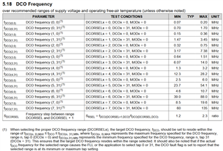
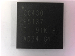
Some of devices (ca 6%) from 91K AD34 lot would not start at low temperature (<10°C). It seems that the 4MHz FLL doesn`t oscillate. At temperature over 20°C the device/application  works well. Processor is in our application over 10 years, without problems. No changes in Firmware, HW or production line have been done in the meantime.

I need to find out the root cause for this defect, urgently.

Thank You.

  • To clarify: Do you calibrate the synth @-10 degrees?

  • What do You mean with calibrate the synth @-10°C? The 4 MHz FLL not start; we cannot it calibrate, if it not start

    Thank You for support..

  • Sorry, too used to issues with calibrating the RF frequency. 

    Not too familiar with the MSP part of this device but I assume we are talking about the FLL part of figure 3-1 in https://www.ti.com/lit/ug/slau259e/slau259e.pdf

    If yes, do you see same if you change the source for FLLREFCLK? (This is for debug, I know you can't change it in application) 

  • Yes, we are Talking about FLL, as describe in Fig. 3.1.

    My Question is, do we have hier a device manufacturer failure or a failure by device setings. As I said, the application works well over the 10 years. And all devices belong to 91K AD34 Date Code.

  • I will also check with QA if we have seen any issues with this batch. I see that one reference signal for the FLL is a oscillator module. If you are using this, have you checked if the oscillator starts up and if not, if it's a xtal issue?

    Would you be able to do a A <-> B swap with both the CC430 and the xtal and see if the issue follows the PCB, the CC430 or the xtal? (swap one thing at the time, swap between a board that pass and a board that fails)

  • We don`t use the xtal in our application.

    The A<->B test shows that the failure migrates with CC430.

    If necessary, I can send You a few processors for test and Analysis.

    Thank You.

  • I have looped in QA for advice on how to handle this further. 

  • Hi,

    so you use the FLL at 4 MHz and if I get it right you use the REFO as REFCLK is this correct?

    When you say it does not start how MCLK and ACLK are looking like?

    If you go down in temp from +20 degC to -10degC is how does MCLK behave does it get slow or faster?

    What is your DCORSEL setting? Have you considered the not below the DCO spec marked in the snapshot?

    Somehow adding snapshots does not work pls go to datasheet #28 on the bottom. Sorry.

  • Hi,

    This is not an issue related to the clock precision or calibration. We have got the more fundamental problem that the FLL does not work at all at somewhat lower temperatures than ambient.What we see is that the REFO seems to work but when the micro tries to switch to FLL further execution of code is stopped. Presumably it loops until the FLL fault flag is cleared but this never happens.

  • Hi Daniel,

    thats what I want to address with my last question on the DCORSEL settings. So as you know the FLL is mixing DCO frequencies according the multiplier and the REF clock. It also modifies the DCO and MOD bits dynamically e.g. when the frequency for a certain DCO tap shifts over temp it either align MOD bits or even DCO bits.


    If now the RSEL setting is not covering the whole specified range including production variation, DCO and MOD bits might reach max or min value which will set the FLL/ DCO fault flag.

    Therefore I request the clock system settings you use? Also please check when the FLL fault flag cannot be cleared how the DCO and MOD bits are looking like?

    That's why I refer to the note below the DCO settings. So for 4 MHZ I I think DCORSEL should be 3 or 4 while initial setting is 2.

  • Hi Walther,

    Thank you for your reply. It helped me to unterstand better the relation between DCO settings and resulting clock.

    I have to precise our statements made earlier: DCOCLK = 16.384MHz, DCOCLKDIV = 4.096 MHz, DCORSEL = 5

    MCLK and SMCLK are both configured to be sourced 1:1 by DCOCLKDIV (this is why I was confused)

  • Hi Daniel,

    thanks a lot, ok so if you use REFCLK = 32768 Hz you multiplier settings for the FLL are 500 right?
    You selected DCORSEL=5 which means

    fDCO(5,0),MAX= 6 MHz

    fDCO(n,31),MIN = 23.7 MHz

    According to the following requirement  fDCO(n,0),MAX fDCO fDCO(n,31),MIN

    it is 6 MHz < 16.384 MHz < 23.7 MHz means it should work from the DCO setting point of view.

    Then I want to see the DCO and MOD bits if you experience the failure at lower temp. The point is that the DCO fault flag only can be set if you reach the max or min of these bits. And this must happen otherwise the flag should be cleared.

    So things which can still happen:
    1. reference clock is wrong --> should be checked via ACLK (you said its correct, pls show me the scope shot or frequency measurement)
    2. FLL settings might have changed --> check all UCS register settings via debugger (pls post snapshot)
    3. the DCO operates out of spec --> disable FLL and set  fDCO(5,0) and fDCO(5,31)  to measure frequency of the DCO frequencies

  • Hi Dietmar

    Right now, we don’t know what component is failing – it may be internal power distribution,  REF0 or FLL. What we can see is that the code execution is halted presumably in the before mentioned loop.

    Unfortunately we cannot access the JTAG anymore since the fuse was blown. The problem was detected by the end customer in the field. Approximately 150 units with one particular day code have this problem.  We suspect a systemic problem in the chip with that day code since we already shipped some 10ks of units in the past without that issue.

  • HI Daniel,

    ok locked JTAG limits the debug capabilities on your site but for sure also on TI site because we cannot production retest these parts anymore or apply any bench testing at all.

    However the CC5137 has E-fuse which can be changed via BSL. Do you still have this capability to unlock JTAG by using the BSL password and prevent main memory erase. In this way you can regain debug access? Or do you have disabled the BSL?
    I think without the information requested before it is hard to make judgements.

    You stated 150 units out of one data code (shipping code) do you know if all of these devices have the same Lot Trace Code (LTC), the marking on the topsite package. If yes can you please share it?

    However it also means these applications worked during your outgoing production test right, let me assume something happened to them in the field. Are there any other commonalities like returning from 1 customer only, any SW or HW changes,....?

  • Hi Dietmar,

    I wasn't aware that the CC5137  has got an E-fuse that potentially can be reset. BSL ist not disabled and the password is available. I will look into this.

    Please see the attached image for the Lot Trace Code

    We have delivered about 300k devices within the past 10 years with identical hardware and firmware. 8 devices have been complained by FORD so far; ca. 140 undelivered defective devices have been found by testing the stock at -10C

    If you want you we send you some defective parts for further analysis (and we provide you with the password)

  • Hi Daniel,

    thanks for letting us know so this means you are no found also units in your stock showing this behavior right?

    Are all these 140 units + 8 field units from the same LTC?

    Before we get parts it would be great if you can unlock them via BSL without erasing main memory. Then pls check if programmed code is still ok. Afterwards attach a debugger and see what happens to the DCO and MOD bits in the DCO fault flag loop.

    If it is confirmed to operate at the border while RSEL bits are set properly and REF clock is ok I think we need to get parts back.

  • Hi Dietmar,

    All the defective 140 + 8 units are from the same LTC. However there are units with that LTC that are ok.


    Right we have problems to unlock the JTAG security fuse with BLS programmers. We have come to believe that this is not possible at all. Can you please clarify whether JTAG security fuse of the CC430F5137 (of the F5xx family) may be unlocked once it has been locked?

    Best regards

    Daniel

  • Hi Daniel,

    what is the status of this case? Were you able to unlock the parts and debug the DCO fault flag together with the DCO bits?

  • Hi Walther,

    So far we have been unsuccessful.  We are suspecting that unlocking that particular microprocessor (CC430F5137) of the F5xx family is not possible at all. Could you please double check on this?

    Regards Daniel

  • Hi Daniel,

    double checked the corresponding ERRATA and data sheet. Normally the device should be delivered with a workable BSL. As long as you have not erased the BSL you should be able to access the device via BSL and either read out the memory content or also overwrite the JTAG lock signature in info memory.
    So what problems are you facing? Is is already to establish BSL connection?

  • Hi Walther,

    We were able to use the BSL. We were able to program a hex file into the flash. But we haven't been able to re-enable the JTAG access.

  • Hi Daniel,

    so you mean the following script example leverage the TI BSL scripter does not work?
    MODE 543x_family COM1
    MASS_ERASE
    RX_PASSWORD
    RX_DATA_BLOCK JTAG_UNLOCK.txt

    with JTAG_UNLOCK.txt

    @17FC
    00 00 00 00
    q

    If this does not work please add the following to unlock the BSL memot

    MODE 543x_family COM1
    MASS_ERASE
    RX_PASSWORD
    RX_DATA_BLOCK OPEN_BSL.txt
    RX_PASSWORD
    RX_DATA_BLOCK JTAG_UNLOCK.txt

    with OPEN_BSL.txt
    @0182
    03 00
    q

  • Hi Walther,

    Thank you for the example scripts. I think the family argument of the MODE command should rather be '5xx'

    What's the contents of  'RX_DATA_BLOCK OPEN_BSL.txt?

  • Daniel,

    according BSL scripter user guide it must be 5xx
    https://www.ti.com/lit/ug/slau655g/slau655g.pdf

    With RX_DATA_BLOCK OPEN_BSL.txt you write 0x0003 to address 0x182 to unlock BSL memory by clearing SYSBSLPE in SYSBSLC register.

  • Can you please give me the content of the file  'RX_DATA_BLOCK OPEN_BSL.txt ?

  • Daniel,

    as posted above the content of OPEN_BSL.txt is nothing else than

    @0182
    03 00
    q

  • Walther,

    I run the above mentionned script but there's still no JTAG access.

    I searched the documentation and found this:

    My interpreation would be that locking JTAG interface cannot be undone in a device of the 5xx family.

  • Walther,

    We got it working now! We are able to restore JTAG access. Please discard my last post. One of the lines of the hand-made cable between BSL-Rocket and target was not correct.

    Thanks for your support. Can we now send you some defective parts?

  • Hi Daniel,

    perfect I also would have run out of ideas. I will discuss shipping parts with my colleague.

    In the meantime can you do me a favor and attach the debugger in the fail condition when the part hangs in the fault flag polling and read teh DCO and MOD bits to see if we hit the boarder. Finally do what we discussed in the beginning.

    If you can send me a picture of the debugger with the register settings it would help us significantly to better understand whats going on.
    Also please do not reprogram the parts and only attach the debugger to the running target once JTAG is unlocked.

  • Daniel,

    got the approval to trigger the return process for 2 confirmed fail units. Please use the following link to trigger the process: Product returns | Create a return.

    If you bought via disty the disty must be involved as well. If you have any questions please let me know.

    However to accelerate the investigation I want to ask to get the debug results on the setup where you can reproduce it to make decisions on the next step.

  • Dear Mr. Walther,

    We purchased the components from Unauthorized TI Distributor; so I cannot issue the return process. Can You help us to find another way to send these components for analysis?

    Thank You.

  • Dear Mr. Vanci,

    Due to uncertainties in the supply chain regarding chain of custody of the products, TI will only support product verification requests from customers who purchase through authorized distributors.  All other verification requests must be worked through their supply chain.  TI strongly encourages you to purchase all your TI parts either directly from TI or from authorized distributors (http://focus.ti.com/docs/general/distribcountryresults.jhtml) and not from the gray market or brokers.

    Best regards,
    Dietmar Walther

  • Thanks to the newly regained debugging capabilities, we were able to gather some information about the failure.

    The cause is not the clock system; the test against oscillator fault never fails.

    It fails when trying to set the core voltage to level 2 - the CPU behaves erratically (RAM corrupted, PC corrupt). However setting the core voltage to level 1 is ok.

    Regards Daniel

  • Daniel,

    great that you made progress that is why we need you to own the debug and nail down because you know your application and SW better than we.

    With respect to further support I have tell you that TI does not support products purchased outside of TI’s authorized supply chain.

  • Dear Mr. Walther,

    We checked our production stock by -10°C and we found another five components with the same behaviour: 8AK A7H1 (1 piece) and 8AK ATPV (4 pieces). These components have been purchased this time through an authorized distributor. I issued already a complaint to this distributor. Maybe TI will be able to analyze at least these components.

    Thank You.

  • Mr. Vanci,

    thanks with this we are ok to continue. Shipping 2 parts would be fine. Please help to send them with JTAG unlocked so that we can read out and debug the parts at TI.

  • Dear Mr. Walther,

    I need to wait the Distributor Tracking# / SCAR# from our supplier to finish the product return request. Daniel is also next week absent.

    Thank You for Your Support. 

  • Dear Mr. Walther,

    We tried to get a return number from our distributor, but we were refused because the components are older than one year.

    What can we do now? The components must be analysed to find out the root cause, even they are older than one year.

    Thank You.

  • Mr. Gheorghe,

    we will check internally how to proceed and let you know but can you please my request posted earlier done:

    In the meantime can you do me a favor and attach the debugger in the fail condition when the part hangs in the fault flag polling and read the DCO and MOD bits to see if we hit the boarder. Finally do what we discussed in the beginning.

    If you can send me a picture of the debugger with the register settings it would help us significantly to better understand whats going on.
    Also please do not reprogram the parts and only attach the debugger to the running target once JTAG is unlocked.

    I think this would help significantly to judge the behavior better.

  • Dear Mr. Walther

    I was indeed able to regain JTAG access to the device. So I was able to pinpoint where the problem starts in the source code.

    Contrary what I said earlier the fault does not seem to be related to the clock system but rather to vcore.

    What I observed was that the RAM content was completely corrupted when the Vcore voltage was raised from level 1 to level 2.

  • Dear Mr. Vanci,

    What distributor did you purchase this material from? This will be helpful for us to determine how to proceed.

    Thanks and regards

    Dag Grini

  • Dear Mr. Grini,

    The distributor is EBV Elektronik GmbH & Co. KG.

    Thank You for support.

    Gheorghe Vanci