A related question is a question created from another question. When the related question is created, it will be automatically linked to the original question.
If you have a related question, please click the "Ask a related question" button in the top right corner. The newly created question will be automatically linked to this question.
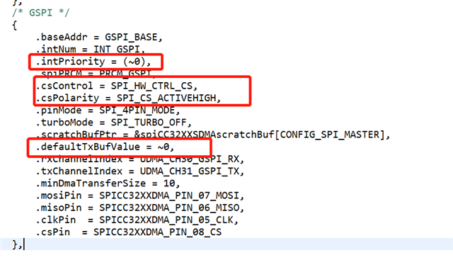
The main practical difference that a customer will notice is that SPI_HW_CTRL_CS deasserts CS between each word during a transfer, while SPI_SW_CTRL_CS keeps it deasserted through the entire transfer. The customer should look at the documentation of their SPI slave device timing diagram and see what it expects - sometimes connected SPI slave devices only support one of those CS methods.
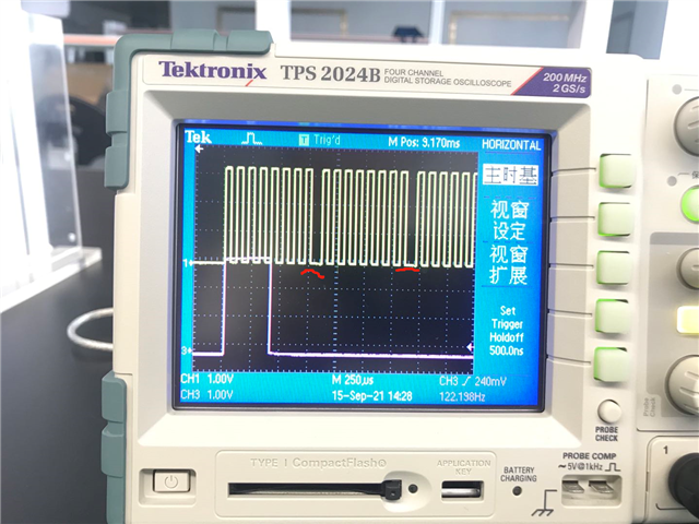
The customer used SPI of LAUNCHXL-CC3235SF to send 0XF0 to ADS1299 directly. Why does a waveform with a relatively large bandwidth appear every eight waveforms? And there is no data sent with so many clocks in between. The customer keeps sending 0xf0 cyclically, but no data is sent after so many cycles. What is the reason?
Are you referring to the gap in SPICLK, what you've highlighted in red on the oscilloscope? That gap is normal and cannot be changed with the CC32xx SPI HW. It shouldn't have a significant performance impact on the system.
As for "no data is sent after so many cycles" could you clarify this, are you referring to that SPICLK gap or something else?
SPI always sends 0xf0 data. It is reasonable to send one data in eight clock cycles, but what the customer sees on the oscilloscope is that after seeing 0xf0, the second data will be sent after many clock cycles(not 8 clock cycles). Why? ?
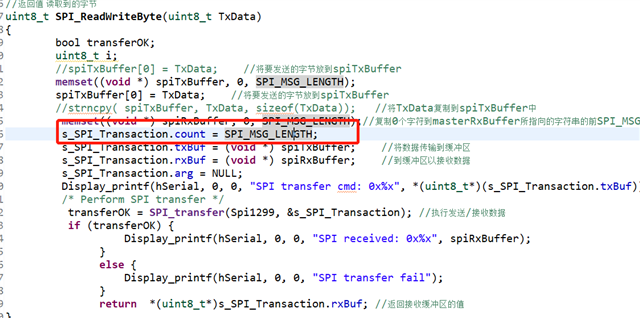
What is the code that the customer is using? Are they trying to perform 0xf0 sends with a SPI transfercount of 1, or are they using something different?
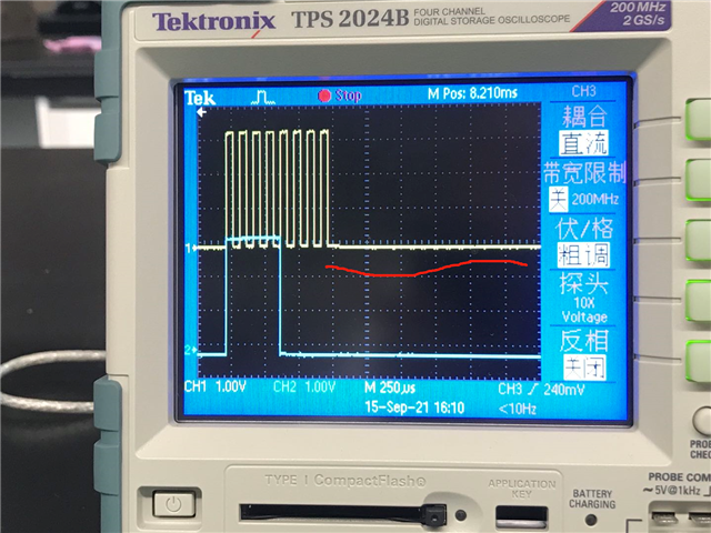
If the customer is simply performing SPI_Transfer() with a transfer size of 1, there is a lot of overhead in the function call that will slow down the actual observed transmission of data. Could they reduce the time resolution, so that I can see about how long that delay is on their SPI transmission?
Thanks for the detail. It looks like they send one byte at a time, and have quite a bit of overhead in their function with the UART printing and other functions. They might want to look into how they can make their code for efficient. For example, if they don't perform the Display_printf(), is the delay reduced?
It seems that it serves as the transaction's (TX) buffer size that is set to all zeroes except for the first byte which is set to the user data (0xf0).