This thread has been locked.

If you have a related question, please click the "Ask a related question" button in the top right corner. The newly created question will be automatically linked to this question.

CC3220MODA: Trouble Flashing CC3220MODASM2MONR Over UART Through Launch-CC3220MODASF Board

Part Number: CC3220MODA
Other Parts Discussed in Thread: UNIFLASH, CC3220SF, CC3220S, SYSCONFIG, CC3220MOD

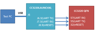
Hi there, I've been attempting to flash a standalone CC3220MODASM2MONR chip on a simple breakout PCB we made, but have been running into a few problems. We're attempting to flash the standalone chip over UART by using the procedure described in the Production Line Guide, which uses the Launch-CC3220MODASF as an intermediary board (see image below).


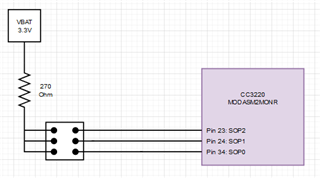
We have these jumpers on the launchpad removed: GND, VBAT, RX, TX, RST. The top pins shown in green in the image below are being used to connect to the standalone chip. VBAT is being used to as a power source for the chip and the SOP pin pullup resistor, and the chip's breakout board and SOP pulldown resistors are grounded via GND.


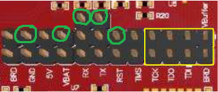
Our UART connections between the Launchpad and breakout board are set up like this:


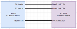
Our SOP pin external pullup/pulldown connections are set up like this:


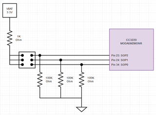
We've tried using Uniflash to connect to our standalone MCU using the described setup in several SOP configurations (SOP2, SOP1, SOP0): (1 0 0), (0 1 0), (0 0 1), (0 0 0)
and several different device selections in Uniflash: the auto detected CC3220SF launchpad, CC3220S(BOOTLOADER), CC3220SF(BOOTLOADER), CC31XX / CC32XX.
For the flashing attempts that requested a COM port, we've tried both COM5 (XDS110 Class Application / User UART) and COM6 (XDS110 Class Auxiliary Data Port).
All attempts have resulted in either one of two errors, being "Bootloader is unsuccessfully invoked!" or "Operation failed: Error: SLImageCreator.exe: BootLoaderError, Timeout reading data".

I realize we've been somewhat making stabs in the dark with our flash attempt configurations. It's been a little difficult to understand the correct and exact process we should be going through to properly flash our standalone MCU. Any help in answering the following questions would be wonderful.

1. Are our hardware connections correct?
2. What SOP pin configuration should we be using? From the Production Line Guide, it says we should be using (1 0 0) for UARTLOAD or (0 1 0) for UARTLOAD_FUNCTIONAL_4WJ. Does it matter which one?
3. What device should we be selecting in Uniflash?
4. I've read in this post that both the CC3220SF and CC3220S modules require external flash chips.
    https://e2e.ti.com/support/wireless-connectivity/wi-fi-group/wifi/f/wi-fi-forum/903843/cc3220moda-cc3220modasf12monr-vs-cc3220modasm2monr
   We currently do not have any external flash, just whatever memory is included in our CC3220MODASM2MONR chip. Will this cause any issues in the flashing process? Should we perhaps consider switching to the    CC3220MODASF12MONR?
5. What project file should we be using to create our image from? I've been attempting to use the "Programming.sli" file so far located in a project's MCU+Image\syscfg\sl_image\Output path.
6. Any other ideas for how we can troubleshoot our flashing setup?

Thank you very much for any help!

  • Hi Maximillian,

    1. The RX and TX header labels on the LaunchPad refer to the CC32xx signals, so you may want to try switching them. The resistor values on your SOP pins look unusual. Be sure you are following the CC3220MOD datasheet and MOD tab of the hardware design checklist.
      1. You can also request a hardware design review here.
    2. Either SOP 100 or 010 can be used for flashing. The difference is 010 also allows for JTAG.
    3. In UniFlash, be sure you are opening Image Creator by selecting the Serial option for CC32xx (NOT On-Chip). Instructions and screenshots are available in the UniFlash ImageCreator Basics tutorial. Once you start Image Creator, the device type is CC3220S for your module.
    4. The CC3220SF has an additional 1MB executable flash that is used for application execution only (along with the 256kB RAM). For this question, I believe you are asking about the serial flash managed by the network processor. This is required for the CC32xx QFN devices, but it is already included in the modules. See the CC3220MOD datasheet.
    5. Recent versions of Code Composer Studio and the CC32xx SDK support a new tool called SysConfig ImageCreator (similar to UniFlash). This tool is able to generate the Programming.sli, which is the device image that can be loaded over UART to the serial flash. Keep in mind this image is different than the MCU image binary (project_name.bin) that you would add to a new project in UniFlash ImageCreator.
      1. To program a SLI image with UniFlash ImageCreator, see the UniFlash ImageCreator user's guide.
      2. Since SysConfig ImageCreator is now integrated into CCS, you can both build and flash the SLI image from inside CCS. After the project and image is built, find the Flash button in the CCS menu.

    Best regards,

    Sarah

  • Oh I see! Your reply was extremely helpful and we were able to successfully flash a basic LED blinking program to our CC3220MOD chip!

    Replies:
    1. Switching the RX and TX connections did the trick. Our connections are now RX -> RX and TX -> TX from the launchpad to the MOD chip on our breakout board. Our confusion came from following the Production Line Guide where it directs us to connect TX -> RX and RX  -> TX. I changed our SOP pin setup to the following setup based on the hardware design checklist you linked and Figure 10-1. CC3220MODx Typical Application Schematic in the CC3220MOD datasheet.

    I missed the fact that the MOD package includes internal pulldown resistors for the SOP pins. My original incorrect SOP resistor values were based on this note in our Launch-CC3220MODASF's User Guide.


    2. Good to know.
    3. Thank you for clarifying this, we were able to connect to the MOD chip using the Uniflash setup you described.
    4. I see, yes it must have been the serial flash I was referring to.
    5. Great to know! We were able to flash our test program using the integrated flashing tool inside CCS.