This thread has been locked.

If you have a related question, please click the "Ask a related question" button in the top right corner. The newly created question will be automatically linked to this question.

LAUNCHCC3220MODASF: UART parameter setting for RS-485 Modbus

Part Number: LAUNCHCC3220MODASF

Hi,


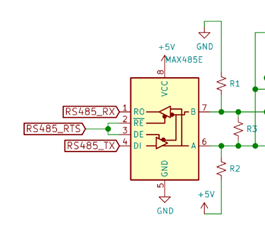
We use rs485 modbus (max485) which is half duplex communication. How to set uart parameter?
We use the UART parameter structure below


UART.c

typedef struct {
UART_Mode readMode; /*!< Mode for all read calls */
UART_Mode writeMode; /*!< Mode for all write calls */
uint32_t readTimeout; /*!< Timeout for read calls in blocking mode. */
uint32_t writeTimeout; /*!< Timeout for write calls in blocking mode. */
UART_Callback readCallback; /*!< Pointer to read callback function for callback mode. */
UART_Callback writeCallback; /*!< Pointer to write callback function for callback mode. */
UART_ReturnMode readReturnMode; /*!< Receive return mode */
UART_DataMode readDataMode; /*!< Type of data being read */
UART_DataMode writeDataMode; /*!< Type of data being written */
UART_Echo readEcho; /*!< Echo received data back */
uint32_t baudRate; /*!< Baud rate for UART */
UART_LEN dataLength; /*!< Data length for UART */
UART_STOP stopBits; /*!< Stop bits for UART */
UART_PAR parityType; /*!< Parity bit type for UART */
void *custom; /*!< Custom argument used by driver implementation */
} UART_Params;

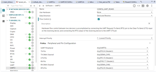
Does it need flow control?

  • Hi.

    Thanks for reaching out, I am looking into this and will follow up tomorrow.

    Kind Regards,

    Rogelio

  • hi
    Any update?

  • Hello Noushadali,

    To get better familiar on how to use the UART peripheral i recommend looking through the Uart2echo example in the SDK.

    https://dev.ti.com/tirex/explore/node?node=A__AAQFAEWlt8mkqF8DfPTC7A__com.ti.SIMPLELINK_CC32XX_SDK__fc2e6sr__LATEST

    I believe you dont need rts/cts do communicate with rs485 but I would double check the uart specifications of the device you wish to communicate with (MAX485)

    Kind Regards,

    Rogelio

  • hi,

    Now I am using UART2 library. I think MAX 485 needs RST pin. When I enable flow controller on UART2, I can't write Modbus frame Tx pin, but disabling flow controller, I get proper Modbus frame from same pin. Why does it behave this way?
     
    pin configuration UART2


    code snippet

    void UART_test() {
    // Initialize UART2 parameters
    UART2_Params params;
    UART2_Params_init(&params);
    params.baudRate = 9600;
    params.readMode = UART2_Mode_POLLING;
    params.writeMode = UART2_Mode_BLOCKING;
    params.readReturnMode=UART2_ReadReturnMode_PARTIAL;
    // Open the UART
    UART2_Handle uart;
    uart = UART2_open(CONFIG_UART_RS485, &params);

    // Check if UART opening was successful
    if (uart == NULL) {
    // Print an error message and return or handle the error appropriately
    Display_printf(display, 0, 0, "Error opening UART\n");
    return;
    }

    // Write the Modbus frame to the UART
    uint8_t modbusFrame[] = {0x01, 0x03, 0x00, 0x01, 0x00, 0x01, 0xC4, 0x39};
    int32_t writeStatus = UART2_write(uart, modbusFrame, sizeof(modbusFrame), NULL);

    if (writeStatus < 0) {
    // Handle error writing to UART
    Display_printf(display, 0, 0, "Error writing to UART\n");
    }

    // Read the response from the UART

    int32_t readStatus = UART2_read(uart, buffer, BUFSIZE, &bytesRead);

    if (readStatus < 0) {
    // Handle error reading from UART
    Display_printf(display, 0, 0, "Error reading from UART\n");
    } else {
    // Process the received data in 'buffer'
    Display_printf(display, 0, 0, "success reading from UART\n");
    Display_printf(display, 0, 0,"readbytet size %d\n", bytesRead);
    // Print each byte in hexadecimal format
    for (size_t i = 0; i < bytesRead; i++) {
    Display_printf(display, 0, 0,"Byte %zu: 0x%02X\n", i, buffer[i]);
    }
    }
    // Close the UART
    UART2_close(uart);
    }


    Modbus schematic 


  • Hi,

    You assumption is wrong. You should not use hardware flow control. You should set RTS pin manually by GPIO.

    Jan

  • hi,
    I tried RTS pin as GPIO then how to control that GPIO pin during write and red operation? .I tried to set gpio as output and make gpio high before write operation and make it low after write operation but no response from Modbus.

    code snippet

    GPIO_write(CONFIG_GPIO_0, 1);
    // Write the Modbus frame to the UART
    uint8_t modbusFrame[] = {0x01, 0x03, 0x00, 0x01, 0x00, 0x01, 0xC4, 0x39};
    int32_t writeStatus = UART2_write(uart, modbusFrame, sizeof(modbusFrame), NULL);
    GPIO_write(CONFIG_GPIO_0, 0);

    At this point, I observe that the timing digram TX and GPIO are also incorrect. Below is the actual timing diagram I observed during MAX485 communication with ESP (esps I use Tx, RX and RTS pins)

  • Hi,

    Hard to say why you see different data output at TX line without deeper debugging. But from your image above it looks DE pin state correct.

    Make sure that your DE signal have proper ahead of time before data TX (see switching characteristics from MAX485 data-sheet).  But this will not fix your issue with RX line.

    Jan

  • hi
    How to manually set RTS pin via GPIO to read and write? When I enabled flow control the Tx line received no data. If we disable receiving data on the same TX pin.

    flow control disabled


    flow control enabled


    How to fix it?

  • Hi,

    I think your issue is related to CTS pin when flow control is enabled. You have configured CTS pin but it is likely not used. That means UART peripheral "think" that other side is busy and not sent data. For more details how UART peripherial at CC3220 works see TRM.

    Jan

  • hi,
    When I connect launchpad Tx, Rx, RST and CST directly to the logic analyzer during the UART write operation


    Why is the CST pin always high? So no data is received by TX

  • Hi,

    What state of CTS pin did you expect, especially when is not connected to other hardware? CTS (clear to send) is a input pin at from CC3220 side.

    Jan

  • Hi,
    All pins from the launchpad connect directly to the logic analyzer, no other hardware is connected. In this case, what is the nature of the CST pin?

  • Hi,

    Sorry, describing how RTS/CTS hardware flow control works is out of scope this forum. At internet you find many many articles at this topic.

    Jan

  • Hi,

    I have successfully tested my RS485 Modbus communication using a logic analyzer when I use a GPIO pin to control the RE & DE pins of RS485. However, I'm currently experiencing an issue where I cannot receive the Modbus response through the Rx pin on the Launchpad. When attempting to read the size of the read byte, only a single byte is displayed, and the read buffer appears to be empty. Is there a potential issue with my read function?

    code snippet:

    size_t bytesRead;
    uint8_t buffer[25];

    void UART_test() {
    // Initialize UART2 parameters
    UART2_Params params;
    UART2_Params_init(&params);
    params.baudRate = 9600;
    params.readMode = UART2_Mode_BLOCKING;
    params.writeMode = UART2_Mode_BLOCKING;
    params.readReturnMode = UART2_ReadReturnMode_PARTIAL;
    // Open the UART
    UART2_Handle uart;
    uart = UART2_open(CONFIG_UART_RS485, &params);
    // Check if UART opening was successful
    if (uart == NULL) {
    // Print an error message and return or handle the error appropriately
    Display_printf(display, 0, 0, "Error opening UART\n");
    return;
    }
    while(1){
    GPIO_write(CONFIG_GPIO_0, 1);
    // Write the Modbus frame to the UART
    uint8_t modbusFrame[] = {0x03, 0x03, 0x00, 0x00, 0x00, 0x01, 0x85, 0xE8};
    int32_t writeStatus = UART2_write(uart, modbusFrame, sizeof(modbusFrame), NULL);
    delayMilliseconds(8);
    GPIO_write(CONFIG_GPIO_0, 0);
    if (writeStatus < 0) {
    // Handle error writing to UART
    Display_printf(display, 0, 0, "Error writing to UART\n");
    }
    sleep(2);
    // Read the response from the UART

    uint32_t readStatus = UART2_read(uart, buffer, sizeof(buffer), &bytesRead);
    Display_printf(display, 0, 0,"readbytet size %d\n", bytesRead);
    if (readStatus != UART2_STATUS_SUCCESS) {
    // Handle error reading from UART
    Display_printf(display, 0, 0, "Error reading from UART\n");
    } else {
    // Process the received data in 'buffer'
    Display_printf(display, 0, 0, "success reading from UART\n");
    // Print each byte in hexadecimal format

    Display_printf(display, 0, 0," data: %x\n", buffer[1]);
    Display_printf(display, 0, 0," data: %x\n", buffer[2]);
    Display_printf(display, 0, 0," data: %x\n", buffer[3]);
    Display_printf(display, 0, 0," data: %x\n", buffer[4]);
    Display_printf(display, 0, 0," data: %x\n", buffer[5]);
    Display_printf(display, 0, 0," data: %x\n", buffer[6]);
    Display_printf(display, 0, 0," data: %x\n", buffer[7]);

    }
    sleep(5);
    }
    // Close the UART
    UART2_close(uart);
    }

    console log:

    readbytet size 1
    success reading from UART
    data: 0
    data: 0
    data: 0
    data: 0
    data: 0
    data: 0
    data: 0

    logical 
    analyzer:


    pin configuration:


  • hi
    Any update?

  • hello,
    any Update?