This thread has been locked.

If you have a related question, please click the "Ask a related question" button in the top right corner. The newly created question will be automatically linked to this question.

CC3220S-LAUNCHXL: Having trouble using an external MCU to program the CC3220S.

Part Number: CC3220S-LAUNCHXL
Other Parts Discussed in Thread: CC3220S, UNIFLASH

Hi,

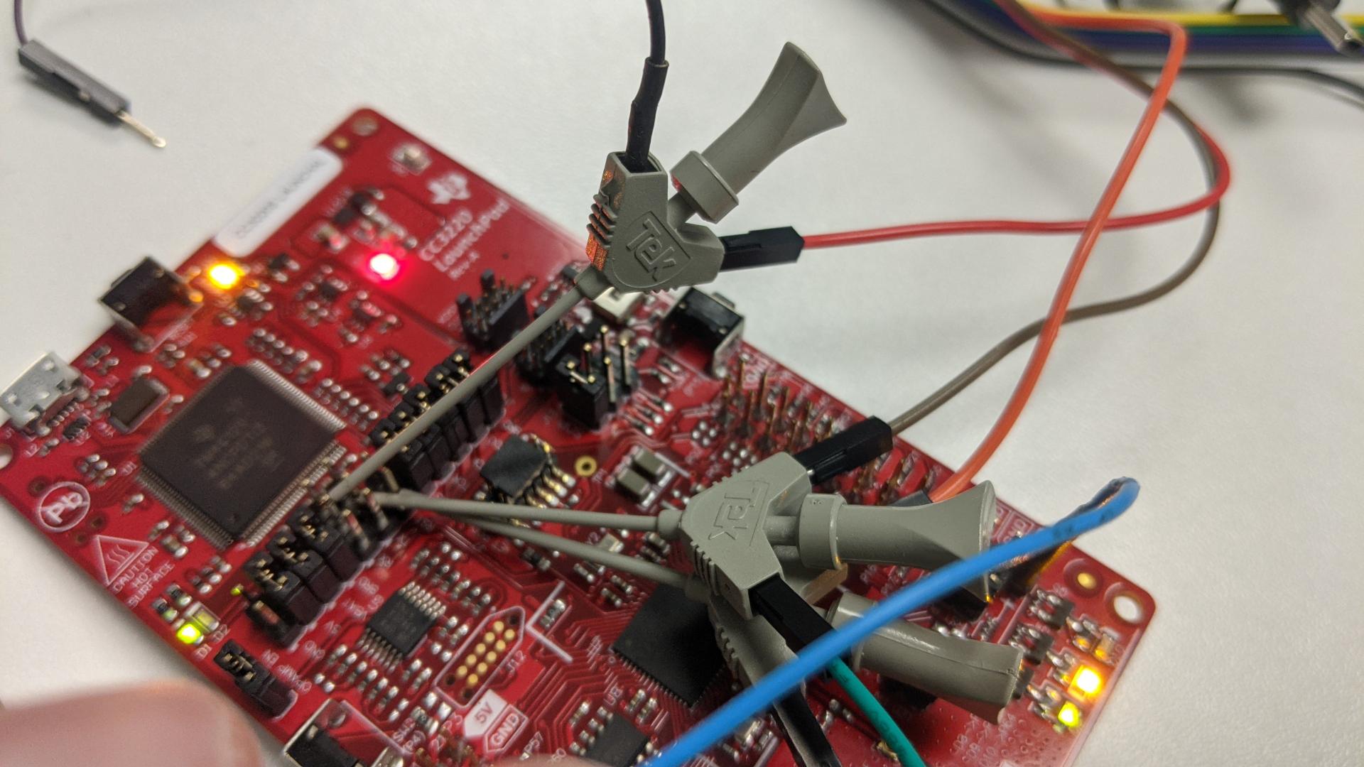
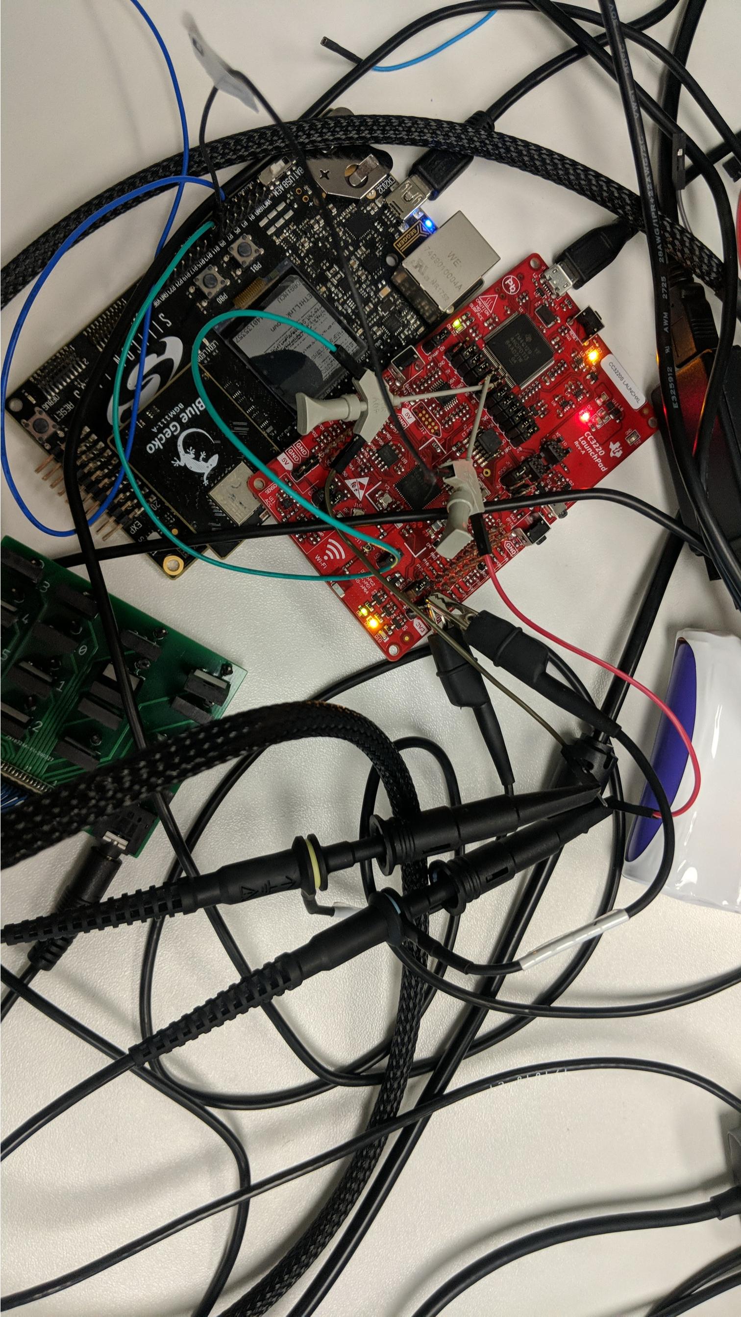
I am currently trying to program the CC3220S on the CC3220SLaunchXL board using a BGM111. My connections between the launchpad and BGM are the following:

BGM --> CC3220S

UART RX ->  UART_Tx (J5 Tx, middle pin)

UART TX -> UART_RX (J6 Rx, middle pin)

nReset pin -> nReset (J3 bottom pin (towards the cc3220s mcu))

SOP connections are:

1(2)-0(1)-0(1)

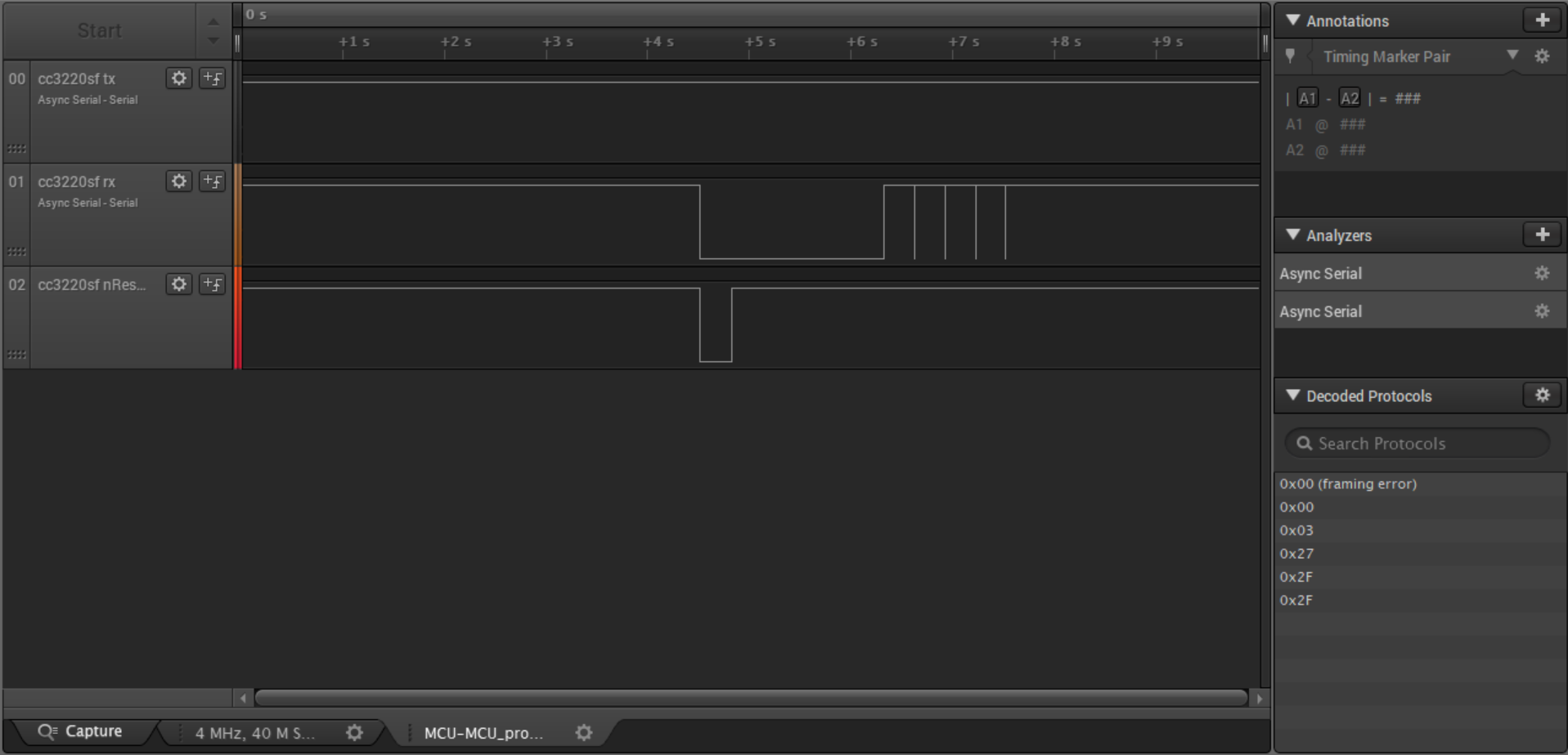
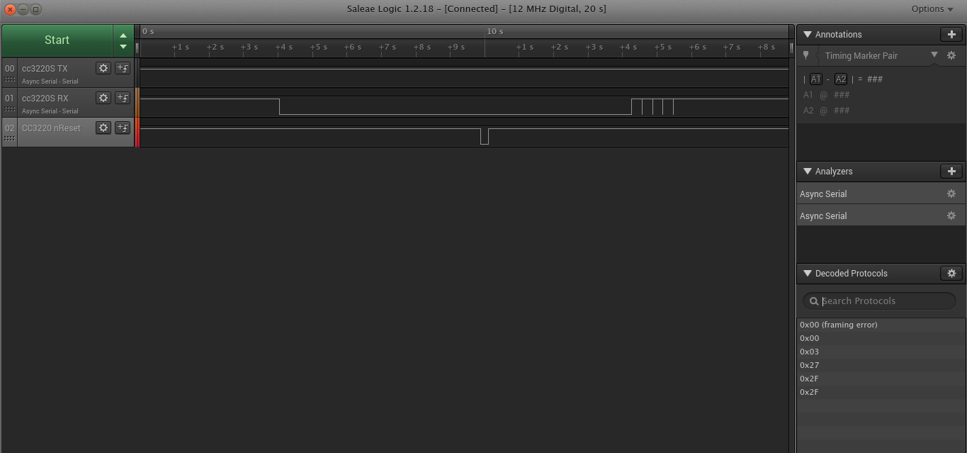
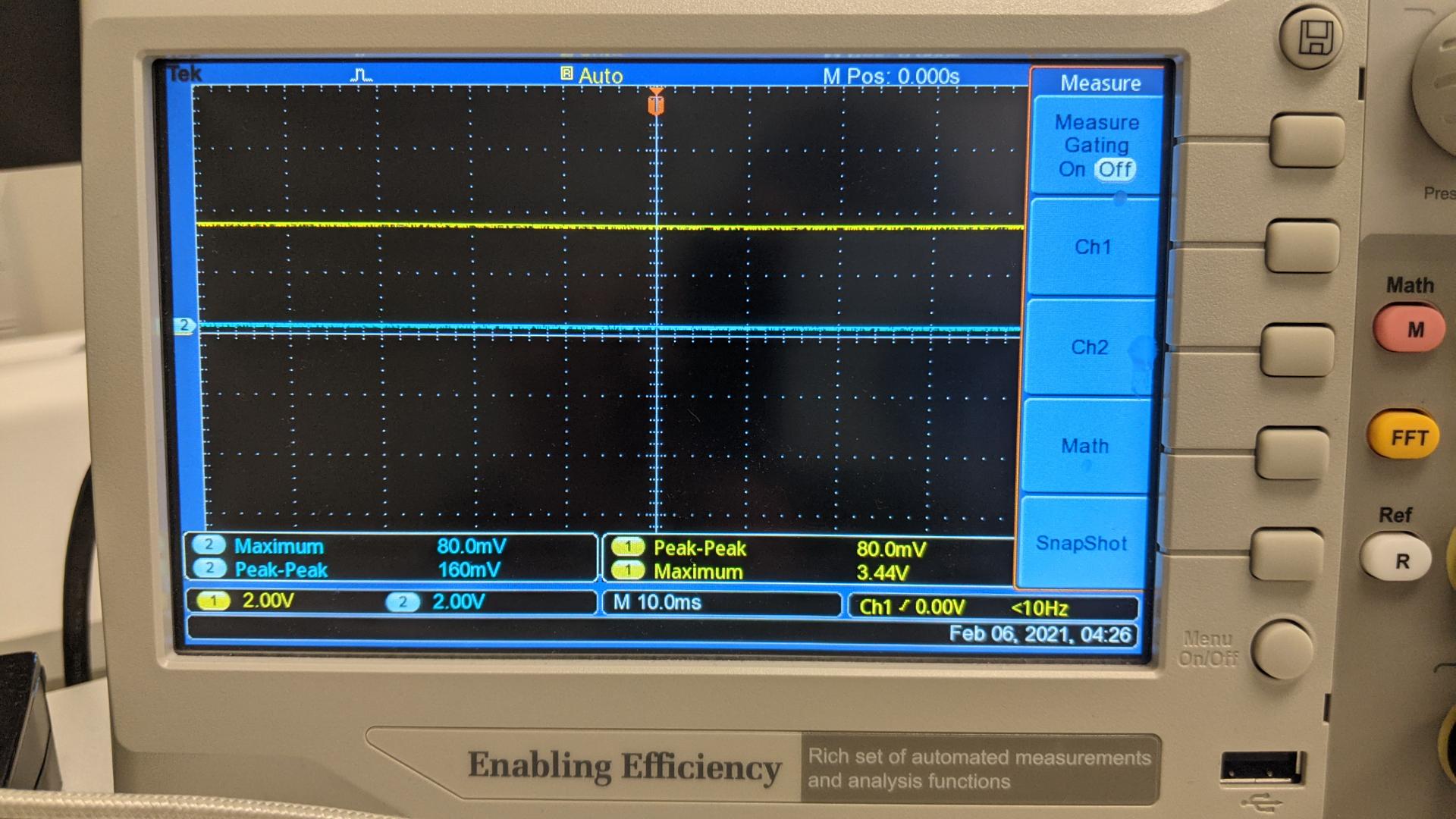
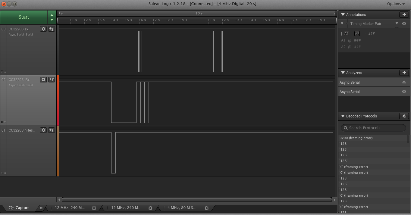
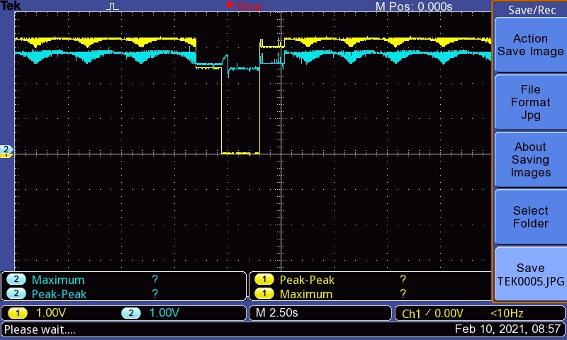
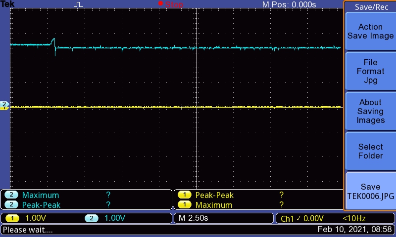
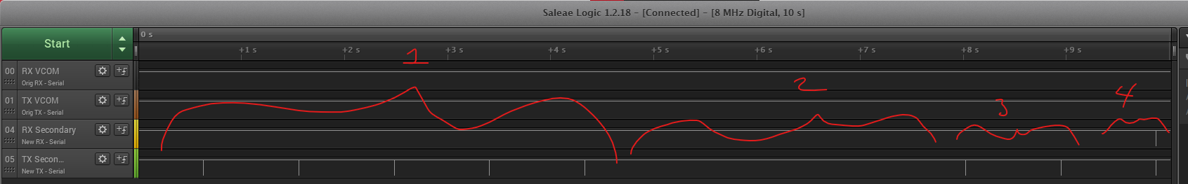
On the BGM side I wrote code to toggle the nReset pin, while I held the RX pin in reset for a bit. I know I am supposed to see a 0xCC, an ack command, on the TX pin but I am not seeing this. I also tried to send multiple different commands to see if there was any response but I still didn't notice anything. I have attached a screen shot of it the logic file for reference. Any help is really appreciated! 

Btw, The UART setup is using 921600 baudrate.

Thank you!

Vasav

(The image says SF but its because I forgot to change the name...

  • Hi,

    Are you ensuring that the CC3220 is powered during your programming sequence?

    At first glance the rest of your setup looks correct, so I will need to investigate some more as to what could be causing your issue. Can you provide a picture of all the connections you have from the BGM111 to the CC3220 for me to review?

    Regards,
    Michael

  • HI Michael,

    Here are the pictures. I think the power is being provided through out the programming sequence. The 3.3V and GND are also connected to the BGM pins. 

  • Hi,

    Thanks for providing the pictures of your setup. The wiring appears to be correct, but given that you are still running into issues we should try to isolate the problem into two parts.

    First, we can check to see if your reset signal is working correctly and actually putting the CC3220 into a reset state. To do this, please run a test where you have only the reset line from your BGM111 connected to the CC3220, and otherwise have the CC3220 connected as default, to the onboard debugger. Then, use Uniflash to program the CC3220, but use the BGM111 to toggle reset as needed. When you connect, and when you program the CC3220, Uniflash will attempt to reset the CC3220 through the XDS110 debugger at the beginning of the connect/programming process. At this stage, try using the BGM111 reset and seeing if that allows the CC3220 programming process to proceed.

    Next, we can see if the UART break signal is being set correctly. For this test, keep your UART lines from the BGM111 connected, but otherwise have the launchpad as default. To check and see if the break signal is recognized, set the break signal from the BGM111 and then press the reset button on the launchpad to manually toggle reset. Do you see the expected response from the CC3220?

    Finally, it's worth checking to see if the powering of the CC3220 might be the issue. You should be able to use the USB power input to continue powering the CC3220 even if you are providing UART and reset from the BGM111. If you power the CC3220 over USB but use the same BGM111 UART and reset setup, do you see different behavior?

    Let me know what are the results of the tests above.

    Regards,
    Michael

  • Hi Michael!

    Here are my notes about the tests.

    Testing the Reset Pin:

    • Method/Setup:
      • Connected the Launchpad to USB port
      • Connected the BGM kit to the USB port
      • Only connection between the Launchpad and BGM kit is Reset pin
        • note: I had to disconnect the power and gnd
        • SOP pins are changed also to 0(2) - 1 (1) - 0(0)
        • UART_RX and UART_TX jumpers are connected to the on-board debugger
      • On the BGM I added a breakpoint right before and after the reset pin is toggled.
        • Reset pin config is Pull-up and default state is Set.
        • The code for toggling basically follows the following: Set(default) -> Clear -> wait 300ms-> Set
      • After setting everything up, I used uniflash to get the version from the Bootloader, since this requires a reset command.
    • Results and notes
      • The device was able to detect the reset and retrieve the Bootloader version however it was a bit finicky.. I had to power cycle the board a few times before it became more reliable.
      • I also tested the SOP connection as 1(2) - 0 (1) - 0(0), and I was also able to get the bootloader version

    Testing the UART lines

    • Methods/Setup
      • The UART RX and UART TX are connected as before.
      • The nReset connection between the BGM And the CC3220 has been removed and the jumper is added back on
      • nReset probe is now probing J8 bottom left corner pin (based on the schematic and the altium files this is the mcu Reset pin)
      • SOP connection is set to 1(2)-0(1)-0(0)
      • The power connection between the launchpad and the BGM is removed
        • They are both powered individually using a separate USB cable going to the same USB hub (I don't think this should be a problem since this setup worked for the reset test)
      • In the code I have a breakpoint while the RX pin is held low giving me time to toggle the reset button manually
      • Side note: the BGM library doesn't provide a nice way to send a break signal so to mimic this I have the RX pin configured as a GPIO pin, which is set to pull down. Then after a set amount of time I create a logic high signal. Then I configure the pin as an UART pin.
        • I realize this is probably not the best way to do this, but my thinking is that even if I miss the ACK signal on startup I can ask for the version to see if device is in bootloader mode. 

    • Results
      • I didn't notice the the ACK signal on the launchpad TX line. I attached a picture with the logic analyzer stuff
    • I also ran the test again to without having the CC3220TX line hooked up to the BGM at all, in case for some weird reason the pin was being pulled high, but I still didn't notice the ACK signal.

    Power Test:

    • I didn't run this test since for Test 2 I made sure the launchpad and BGM have their own power, and based on a similar setup worked before.

    Thank you for your help!

    Vasav Shah

  • Hi Vasav,

    Thanks for performing those tests. So it looks like the issue is with the UART signals from teh BGM111 to the CC3220. Are you able to use an oscilloscope to check those signals and ensuring that the break signal is reaching the expected levels, and that there is no unexpected noise?

    Also, what are the momentary dips to logic low in the UART TX signal, after the break signal is deasserted. Are these test commands that you're running to see if the bootloader responds?

    Regards,

    Michael

  • Hi Michael,

    Here is a picture of the setup again for your reference:

    I connected the oscilloscope to check the signals also. The beak signal is reaching about 160 mV for the low, and the noise is about 80mv on that line. Here's a picture for the UART break signal in a low state: BTW channel 2 (blue) is the rx line and channel1 (yellow) is the tx line

    In the high state the UART signal reaches about 3.44V with a noise of about 80 mV also. Here are the picture for the signal in a high state.

    In regards to the momentary dips in the logic, yes those are the test commands I am sending to see if the bootloader responds.

    Thanks for your help!

    Vasav

  • Hi Vasav,

    Thanks for providing that information.

    At this point, it does seem like there might be some underlying hardware issue that is causing your issue. As it is looking less likely that this is a software issue, I am looping in a hardware engineer who will be better able to help you. He should get back to you in a day or two.

    Regards,

    Michael

  • Hi Vasav,

    Is there a reason you aren't programming the device directly through the USB connection? From reading through the discussion so far, If you are able to get periodically get bootloader info, then SW is probably "Okay", and maybe its a issue with the HW IO levels. First thing I would do is remove all the jumpers that you don't need - Since you are programming and powering externally, that means all jumpers. SOP can be left in 010 which is flash/func. Test this and let me know.

    BR,

    Vince 

  • Hi Vince, 

    Here are my notes for the test:

    Method/Setup:

    • I removed all the jumpers in the middle row. 
    • I connected 3V3 and GND to the BGM eval kit
    • I connected the UART_RX, UART_TX and nReset pin to the BGM board
    • I connected the SOP pins 0(2) - 1(1) - 0(0)
    • I connected a logic analyzer on all three gpio pins
    • I also connected the o-scope to the UART_RX (channel 2) and UART_TX pins (channel 1)
    • Removed all the breakpoints in my code 

    Results:

    • I am noticing significantly more noise on the RX and TX lines. 
    • I don't think the CC3220S is going into the bootloader mode at all
    • Here are the pictures from the tests.

    I also ran the Test with the UART_TX disconnected to the BGM. Unfortunately the results weren't much better. 

    Let me know about your thoughts for these tests.

    In regards to why we are using the UART to program it is because, on our device, we want to implement OTA as a feature. We have a BGM and CC3220S on the actual device so we want to verify that programming according to this method would work before we make a PCB with this connection. Based on the datasheet we thought this method would work. We know that the CC3220S chip can also implement OTA using a WiFi, but we wanted to ensure that this connection was there as a back-up. If you have a suggestion on a better way to implement this feature please feel free to let us know!

    Thank you for your help!

    Vasav

  • Hi Vasav,

    Can you apply to VCC to the 3v3 in the middle row of headers? Should be the lower jumper you connect to.

    Additionally yes there is an better way to do OTA via API calls - here is some documentation to get started and I'll let Michael comment on this further https://www.ti.com/lit/an/swra510b/swra510b.pdf

    BR,

    Vince 

  • Hi Vince,

    I hooked up the 3.3 to J17 bottom pin. Then I ran the program again, and didn't notice a ACK signal on the TX line. Here are the pictures, Yellow is the RX line and blue is the TX line.

    I ran the program again disconnecting the TX to ensure there wasn't anything weird going on with it, but still didn't notice an ack signal.

    I also decided to manually shorted the RX pin to the GND and then toggle the reset pin, but I still didn't notice anything on the TX line.

    My notes:

    • There is significant amount of noise on these lines, Do you think this would be a problem?
    • Also both the Rx and TX lines are not getting pulled down right away, there seems to be a step in between, do you know what can cause this?

    In regards to the OTA, thank you for this information, I will read into it more and pass the information along to my colleagues and see what they think.

    Thanks for your continuous support!

    Vasav

  • Hi Vasav,

    As Vince mentioned, there are ways to perform OTA updates directly through Wi-Fi.

    Within the CC32xx SDK is the OTA library, which provides the code needed to download an OTA bundle from a cloud server and then update the CC3220 firmware and files. In addition to the document linked by Vince, this SimpleLink Academy module demonstrates how to use the OTA library:

    https://dev.ti.com/tirex/explore/node?node=ACE5ggZRybEJNZUcnzc3ww__fc2e6sr__LATEST

    I'll let Vince comment on the latest hardware observations you've provided.

    Regards,

    Michael

  • Hi Michael,

    Thank you for this information! From what I read and understand this would require a WiFi connection with a vendor where the image would be located. After the connection has been established the OTA lib would handle everything from downloading to install the new image. I was wondering if it was possible to change the process so that instead of using the WiFi for the new image we could use an UART link? I.e. Have the file downloaded via a UART link and then follow the same process the OTA lib follows except omit everything related to WiFi?

    Vasav

  • Hi Vasav,

    You can use a UART link to copy over the OTA bundle. Local OTA, when you're not connected to a cloud server, is possible. In the SDK, there is the local_ota example that you can use for reference. While that example demonstrates how to receive data chunks over HTTP, you can modify it to receive data chunks over UART if you wanted to. See the otaPutCallback() function in link_local_task.c for reference.

    That being said, is there a hard requirement to perform updates over UART? It will likely be more straightforward to perform updates through the cloud, given that your system will have Wi-Fi connectivity, and can easily interface with your servers or preferred cloud vendor to download updates.

    Regards,

    Michael

  • Hi Michael and Vince,

    Thank you for this suggestion, I will try this out and see if it works. In regards to the Wifi connectivity, there isn't a hard requirement, but there are 2 reasons, why we haven't tried this yet. First, adding WiFi in will introduce other security features that might need to be implemented also. Second, I do have a colleague who is attempting to use a tablet to create a WiFi network to which the device will connect but he is still working on this feautre. The purpose of my UART link is to have a backup plan in case he isn't successful. 

     Also Vince, I wanted to follow up on my previous post, do you need to me to run more tests?

    Thanks!

    Vasav

  • Hi Vasav,

    You will likely need to implement security features anyway, if you are performing updates over Wi-FI but connecting to your end-user's phone or other local device. This is needed since attackers could potentially be within Wi-Fi range but outside the home/office/etc where your product gets deployed.

    Also, if you were to use the CC3220 UART in an application and running a UART test such as the uartecho demo from the SDK, are you able to correctly receive data from the BGM111?

    Regards,

    Michael

  • Hi Michael! Wanted to give you an update on something similar I am experiencing. I am running the UART echo example and when I use the serial port, VCOM RX receives the data and VCOM TX is able to echo it, as expected.

    I was curious if I could have another UART on the BGM transmit data every second directly to the VCOM RX and wasn't having any luck. When I hooked it up to the logic analyzer, this is what I see. (No CTS or RTS in this example)

    1 and 3: The secondary TX (TX2) is floating and transmitting every second. This is expected.

    2: TX2 is connected directly to VCOM RX. Expected: VCOM RX receives data from TX2 and mirrors it, and VCOM TX then echoes the data. Actual: TX stays high, exactly as Vasav was seeing in his scenario.

    4: TX2 is connected directly to RX2. Expected: RX2 receives data from TX2 and mirrors it. Actual: works as expected, unlike what happens in example 2.

    Could it be that the JLink debugger built into the development board is holding the RX pin high, and preventing any TX pin from being strong enough to pull it to ground? I tried setting the debug mode from "MCU" to "OUT" to no avail.

  • Hi,

    Is the VCOM referring to the CONFIG_UART_0 UART setup in the uartecho demo?

    To also clarify, TX2 is a BGM111 UART output, correct?

    If I'm understanding this correctly, the CC3220 UART works when it's looping back to itself, the BGM111 UART also works when looping back itself, but when you connect the CC3220 RX to the BGM111 TX, it doesn't work.

    The CC3220 launchpad uses the XDS110 debugger, not a JLink debugger. If you have disconnected the UART header jumpers (J5,J6), which bridge the UART signal from the CC3220 to the XDS110 debugger, then there should be no other devices on the Pin55/57 UART net. Have you disconnected those jumpers?

    Also, when you perform test 2, do you also connect the CC3220 TX and BGM111 RX to each other? The CC3220 UART peripheral might behave unexpectedly if one of the UART lines is left floating.

    Regards,

    Michael

  • This is slightly embarrassing. I should have labeled which TX RX ports belonged to which device. I've performed the test so many times that I don't remember which is which. To summarize, the problem was the JLink on the BGM causing conflicts with the CC3220S TX line. When I connected CC3220S RTX lines to each other I believed I had a similar issue with its XDS111. Everything is now working fine once I removed those conflicts.