This thread has been locked.

If you have a related question, please click the "Ask a related question" button in the top right corner. The newly created question will be automatically linked to this question.

SPI Clock problem in 16Mhz

Other Parts Discussed in Thread: CC3200, ENERGIA

Hi All,

I have noticed SPI clock goes wrong when goes wrong at 16 Mhz, the problem exist in 8Mhz but it not noticeable.

Also updated CC3200 LauchPad XL to latest firmware 0.5.2.0.1

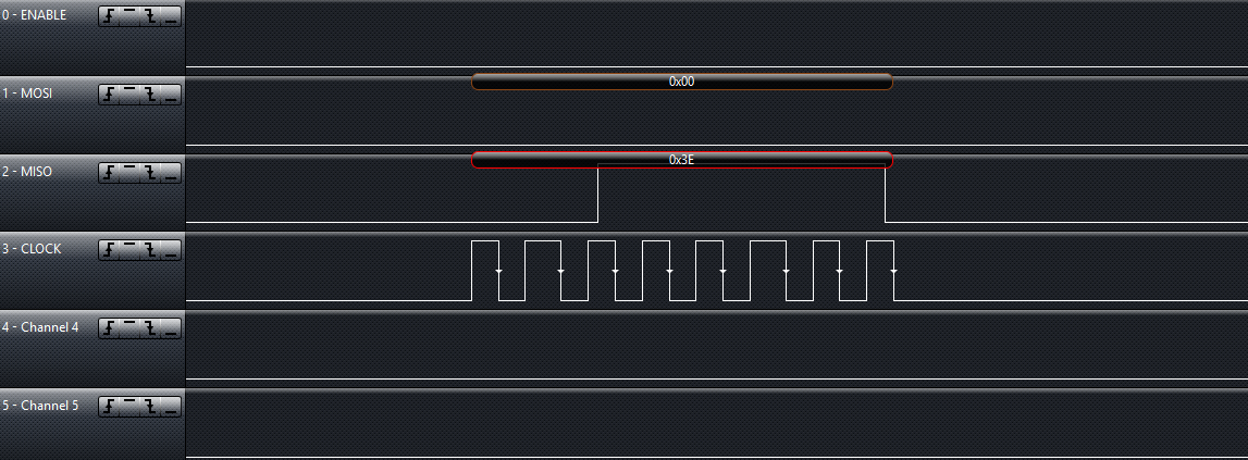
This is SPI at 8Mhz. As you see all clock cycle are not equal and frequency change between 7.14 Mhz to 8.33 Mhz

At 16 Mhz it get worse frequency goes from 16.67 Mhz to 25 Mhz

This is when we have hardware control

--------

MAP_SPIConfigSetExpClk(SSIBASE,MAP_PRCMPeripheralClockGet(PRCM_GSPI),
MAX_BITRATE/divider, SPI_MODE_MASTER, SSIMode,
(SPI_HW_CTRL_CS | SPI_3PIN_MODE |SPI_TURBO_OFF |SPI_CS_ACTIVELOW |SPI_WL_8));

MAP_SPIEnable(SSIBASE);

------

In case of software control, clock doesn't over 8Mhz and in all measurement sampling rate for Saleae is 50Mhz

Thanks,
Ali

  • Hi Ali,

    It seems that the problem you are seeing isn't with the simpleLink WiFi device, but with the tool you are using to sample the lines.
    From our experience it isn't accurate enough when sampling high frequencies.

    If you will try to probe the lines with an Analog scope or a stronger logic analyzer you will see that the lines are just fine.

    Thanks,
    Alon

  • Hi Alon,

    I'm not sure this issue is due to the LA being used. A 50MHz  sample rate should be fine for 8Mhz and even 16Mhz, I have the entry level version of the Saleae and can measure these rates with its maximum 24Mhz sample rate.

    I believe this issue is related to the Clock Tree and what frequencies can be successfully generated using dividers etc. I have not been able to find the Clock Tree for the CC3200, so cannot verify what is possible. Another cause may actually be "issues" or "limits" to the SPI clock on the CC3200. I have noticed other behaviour which indicates it works differently to the Tiva C SPI Clock.

    I do not have an analog scope to test, but I suspect you guys should have one in the office. Perhaps give this a quick test your self. I believe you will find the same behavior that Ali is seeing.

    Glenn

  • Well same code works fine at 8Mhz but return wrong data at 16Mhz. SPI main driver for reading is clock.

    And if check clock you see is not right. I doubt issue is Logic Analyzer

  • Hi Ali,

    Understood, I've missed that fact, sorry for that.

    We will look into it and get back to you.

    Thanks,
    Alon

  • Thanks, well I should be more clear about it ticket.

    Thanks,
    Ali

  • Hi Ali,

    Apologies for delayed response.

    Pls note that the SPI can only generate clocks which are interger divider of 40 MHz. ( 20MHz, 13.33MHz, 10MHz, etc)

    Below is a snapshot of SPI interface running at 20 MHz taken using an LA with 200 MSa/s. As you can see the SPI clock is very stable. It might be a problem with the tool you are using to sample the lines


    Let me know if this answers your query.

    Thanks and Regards,

    Praveen


  • Hi Praveen,

    As you state, there are specific frequencies that the SPI clock will run at due to the clock tree (i.e. dividers).

    Hence I am confused as to why you are suggesting the LA is the problem. I am sure that if you set up SPI at 16Mhz, you will see the same result as shown by Ali in his first post.

    Glenn.

  • Hi Glenn,

    You can't set SPI clock at 16 MHz. The SPI divider can't take fractional values, it is an interger divider.

    A call to  MAP_SPIConfigSetExpClk() with 16MHz as parameter will set the divider to divide by 2 not by 2.5 which is 40/2 = 20 MHz.

    But due to the LA not being able to sample the clock properly it showing a variation from 16.67 MHz to 25MHz

    Thanks and Regards,

    Praveen

  • Hi Praveen,

    Praveen Kumar N said:
    You can't set SPI clock at 16 MHz. The SPI divider can't take fractional values, it is an interger divider.

    That is what I was saying.

    Well basically, what I am saying is that the Clock does this funny jumping between frequencies when you try and set it to a non-supported frequency. I have seen this happen on the Tiva C also.

    Or are you saying that the image you have included above, was you attempting to set the SPI Clock to 16MHz? (You did say you set it to 20Mhz and not 16Mhz)

    If you have not tested SPI by attempting to set it at 16Mhz, it would be great if you could give it a go and let us all know the outcome.

    Thanks,

    Glenn.

  • Hi Glenn,

    The cc3200 SPI hardware itself doesn't support generating 16 MHz. It just has an integer clock divider sourced by 40MHz clock. Which means the division values can be 1,2,3,4,5 and so on.

    To generate and test 16 MHz from 40 MHz source clock you require a division of 2.5. Which is not possible on the hardware.

    Thanks and Regards,

    Praveen

  • Hi Praveen,

    I know it will not....But what happens when you try and set SPI to 16Mhz just as Ali has done?

    Do you get the same result as shown by Ali's first post or do you get the 20Mhz result shown by you?

    It would great to understand how things work in practice as opposed to the theory.

    Glenn.

  • Hi Glenn,

    With the following configuration you will get a stable 20 MHz SPI clock.

    MAP_SPIConfigSetExpClk(GSPI_BASE,MAP_PRCMPeripheralClockGet(PRCM_GSPI),
                         16000000,SPI_MODE_MASTER,SPI_SUB_MODE_0,
                         (SPI_HW_CTRL_CS |
                         SPI_3PIN_MODE |
                         SPI_TURBO_OFF |
                         SPI_CS_ACTIVEHIGH |
                         SPI_WL_8));

    Thanks,

    Praveen

  • Hi Praveen,

    Thanks, I appreciate the extra effort you put in. It's good to know what actually happens when you put in a non-supported frequency.

    Glenn.

  • Thanks Glenn, Ali,

    Pls verify the answer to close this thread if your question is answered.

    Regards,

    Praveen

  • Ok, let assume my measuring are wrong, which I will verify that.

    But why I can ready correct data at transfer when frequency is 8Mhz but not at 16Mhz?

    And I tested that code as well, same result.

    Thanks,

    Ali

  • Hi Ali,

    How are you observing the MOSI data? Can you please share more details of your setup. I assume from your previous post you are using 3 pin mode.

    Thanks and Regards,

    Praveen

  • Ali- Your peripheral device being driven over SPI might not support 20MHz, hence it'll run flaky when you set it at "16MHz" since it's not actually running at 16MHz, but is instead running at 20MHz.

    Whereas, when you operate the CC3200 SPI at 8MHz, it's actually running at 8MHz.

    I believe the limitation of the test tool is a big factor here; I tried various settings (Energia 13 w/ CC3200, SPI_CLOCK_DIV1 through 8) and the jitter in the signal was always around 10ns, which happens to be the minimum sample width of the tool (100MHz Saleae Logic16).