This thread has been locked.

If you have a related question, please click the "Ask a related question" button in the top right corner. The newly created question will be automatically linked to this question.

What accuracy can be reached with the timers? -> GPIO interrupt on wrong edge!

Other Parts Discussed in Thread: CC3200

edit 2015-12-01: it seems not an issue with the timers, but GPIO interupt triggering on the wrong edge, please follow this thread to the end.

I was wondering what accuracy I can reach with the internal timer functions?

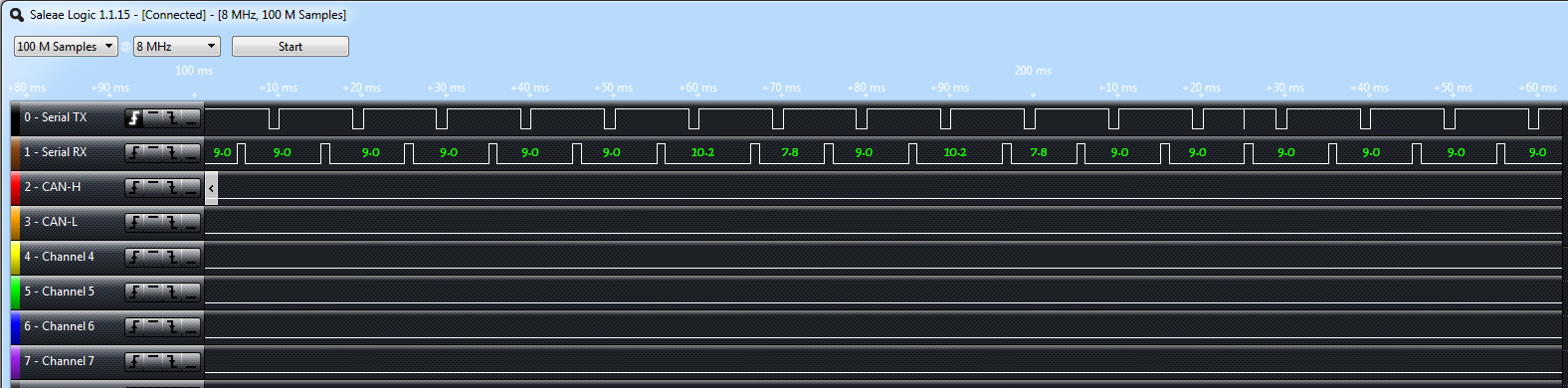
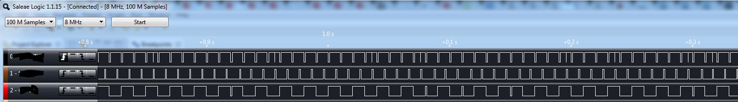
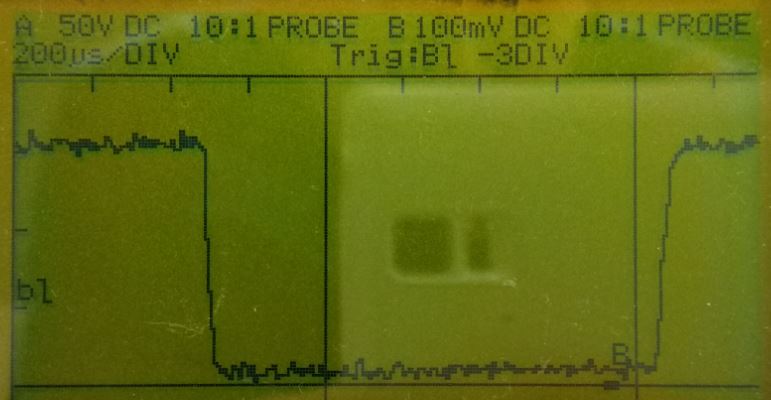
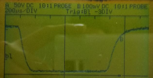
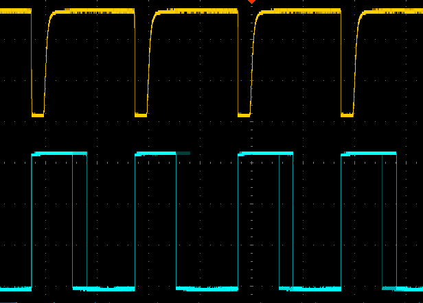
I have a pretty straight forwarded application that starts a timer on a gpio interupt input. The timer controls an other gpio pin. When I run this with a function generator on the input and put both signals on a scope, then I should see a constant distance between the 2 signals (if the timer is reliable).

At run this setup at 50Hz (10ms per puls on input). The timer is delaying 0-9ms fixed value. But my ouput pin (controlled from timer interup) is sometimes 1-2ms too late...

Some code:

on init:

//Initialize Push Botton Switch
	Button_IF_Init(SW2InterruptHandler,SW3InterruptHandler);

	//Enable GPIO Interrupt
	Button_IF_EnableInterrupt(SW2); // not used yet
	Button_IF_EnableInterrupt(SW3);

	//Setup timer A0
	UART_PRINT("Setup timer \n\r");
	Timer_IF_Init(PRCM_TIMERA0, TIMERA0_BASE, TIMER_CFG_ONE_SHOT, TIMER_A, 0); // Configuring the timers
	Timer_IF_IntSetup(TIMERA0_BASE, TIMER_A, TimerA0IntHandler); // Setup the interrupts for the timer timeouts.

void SW3InterruptHandler(void)
{
	unsigned long ulDelay; // unit is 0.1ms

	ulDelay = 50; // 5ms

	//start timer
	Timer_IF_Start(TIMERA0_BASE, TIMER_A, (PERIODIC_TEST_CYCLES / 10000) * ulDelay); // Turn on the timers

	Button_IF_EnableInterrupt(SW3);
}


static void
TimerA0IntHandler(void)
{
	static unsigned char ucState=0;

	// Clear the timer interrupt.
	Timer_IF_InterruptClear(TIMERA0_BASE);

	if (ucState == 0)
	{
		GPIO_IF_LedOn(MCU_GREEN_LED_GPIO);
		Timer_IF_Start(TIMERA0_BASE, TIMER_A, (PERIODIC_TEST_CYCLES / 1000) ); // Turn on 1ms timer to turn of output after 1 ms (ucState=1)
		ucState=1;
	}
	else
	{
		GPIO_IF_LedOff(MCU_GREEN_LED_GPIO);
		ucState=0;
	}
}

Most code copied from examples. I havenot played around with interupt priorities.  In timer_if.c I left this at INT_PRIORITY_LVL_1.

Any ideas? Am I asking to much resolution from this system? 

  • Hi,


    Let me check, will get back to you.

    Thanks and Regards,

    Praveen

  • I connected my logic analyzer to make the timer jitter visible:

    channel 0 is the input signal on which the timer is started (at 6.2ms after falling edge), period is 10ms.

    channel 1 is the output signal triggered from my timer interupt, this on should be 9.0ms low, 1.0ms high (10ms period).

    The timer should be 9.0ms all the time! But sometimes, it jumps to 10.2. Interesting to see is that after a 10.2 there is always a 7.8. So it looks like the timer is sometimes too late, and because I have it fixed at 9.0, its corrected to 7.8. Is it safe to say that my Timer interrupt is hold up by something else?

    To get an idea about the occurance, I measured a lott of periods:

    10.2, 7.8, 10.2, 7.8, 9.0, 9.0, 10.2, 7.8, 9.0, 9.0, 9.0, 9.0, 9.0, 9.0, 9.0, 9.0, 10.2, 7.8, 9.0, 10.2, 7.8, 9.0, 9.0, 9.0, 9.0, 9.0, 9.0, 9.0, 9.0, 9.0, 9.0, 9.0, 9.0, 9.0, 9.0, 10.2, 7.8, 10.2, 7.8, 9.0, 10.2, 7.8, 9.0, 9.0, 9.0, 9.0, 9.0, 9.0, 10.2, 7.8, 9.0

    So in 510ms I got 8 occurances of the timer firing 1.2ms too late.....

  • I have been testing a lot today. But the problem remains, even with interupts on INT_PRIORITY_LVL_0 the behaviour is the same. In my opinion a real time os should not block high priority interupts for 1.2ms..... So what is causing this?

    I also disabled my httpserver task and removed VStartSimpleLinkSpawnTask() to get it to run as stand alone as possible without any change....

  • After a full day, I found the cause of the irregular timing behaviour!

    I got the input signal to trigger on the falling edge, but it seems that it is sometimes also triggered on the rising edge! I made this visible on my logic analyzer. Ch0 is my input signal again, Ch1 the timer that triggers an output, Ch2 is toggled by each falling edge interupt of SW2:

    code related to setting the interupt of SW2 (direct copy of button_if.c from the examples, only modified the edge):

    void Button_IF_Init(P_INT_HANDLER S2InterruptHdl,P_INT_HANDLER S3InterruptHdl )
    {
        if(S3InterruptHdl != NULL)
        {
            //
            // Set Interrupt Type for GPIO
            //
            MAP_GPIOIntTypeSet(GPIOA1_BASE,GPIO_PIN_5,GPIO_FALLING_EDGE);  // GPIO_FALLING_EDGE GPIO_BOTH_EDGES
            
            g_S3InterruptHdl = S3InterruptHdl;
            
            //
            // Register Interrupt handler
            //
    #ifdef SL_PLATFORM_MULTI_THREADED  /* If OS-based application */    
            osi_InterruptRegister(INT_GPIOA1,(P_OSI_INTR_ENTRY)GPIOs3IntHandler, \
                                    INT_PRIORITY_LVL_1);
    #else                            
            MAP_GPIOIntRegister(GPIOA1_BASE, GPIOs3IntHandler);
    #endif    
            //
            // Enable Interrupt
            //
            MAP_GPIOIntClear(GPIOA1_BASE,GPIO_PIN_5);
            MAP_GPIOIntEnable(GPIOA1_BASE,GPIO_INT_PIN_5);
        }
        
        if(S2InterruptHdl != NULL)
        {
            //
            // Set Interrupt Type for GPIO
            //
            MAP_GPIOIntTypeSet(GPIOA2_BASE,GPIO_PIN_6,GPIO_FALLING_EDGE); // GPIO_FALLING_EDGE GPIO_BOTH_EDGES
    
            g_S2InterruptHdl = S2InterruptHdl;
            
            //
            // Register Interrupt handler
            //
    #ifdef SL_PLATFORM_MULTI_THREADED  /* If OS-based application */    
            osi_InterruptRegister(INT_GPIOA2,(P_OSI_INTR_ENTRY)GPIOs2IntHandler, \
                                    INT_PRIORITY_LVL_1);
    #else                            
            MAP_GPIOIntRegister(GPIOA2_BASE, GPIOs2IntHandler);
    #endif    
                                
            //
            // Enable Interrupt
            //
            MAP_GPIOIntClear(GPIOA2_BASE,GPIO_PIN_6);
            MAP_GPIOIntEnable(GPIOA2_BASE,GPIO_INT_PIN_6);
        }
    }
    

    So... Why does it trigger on rising edge when I programmed it as falling edge?


    Is this a bug in the controller????

    Note: I only get this behaviour with a 9ms high, 1ms low signal. With a 5ms high, 5ms low signal from my function generator it works perfectly. I even increased the function generator to 5kHz without this problem, so it seems related to a non symetric signal (e.g. 9ms high, 1 ms low) but I cannot make that with my function generator...

  • No exact appearance of how is circuit connected to your board is here, another can be parasitic coupling from wires of Saleae LA if not a cheap clone china board, this is not a real LA and a scope may be of more help to see what really happen to waveform.
    Your program can be experiencing more interrupt jitter due to latency than accuracy of timer, timer are accurate to clock jiitter and to quantization uncertainity.
    Main issue can be ringing on driving input waveform or some noise from internal generator end stage. Please provide more detail of all setup.
  • I have had issues with the Saleae and the CC3200, especially when attempting to trace while the pins are connected to the peripheral/device that is consuming the signal. I recommend testing without anything attached to the pins, if this is not possible on your board, try the code on a LaunchPad where you can connect direct to the header without anything else involved (except for perhaps an external pull if required...the internal pulls are quite weak on the CC3200).

    Glenn.
  • Well, the LA is just to make a random occurance visible, which is hard to trigger on a normal scope. I am 100% certain that my input sometimes triggers on the rising edge while I have programmed it to trigger only on falling edge! So this thread has no longer to do with the accuracy of the timer (though still an interesting question).

    I am using the normal launchpad board and I am using only the SW3 and GreenLed connection.

    I used the timer to make a 9ms high, 1 ms low signal and feed that through the greenled to SW3 and trigger on falling edge. This works without problems.

    When I connect my hardware that does the same, it sometimes triggers on rising edge.... See above LA pictures for proof. So I was thinking about noice offcourse. I connected a 100nF condensator and also put a ferrite in, but that did not help. On my scope the signal looks good. See picture below (this is without the 100nF, with the 100nF it is just a lot smoother but still the same problem):

    The signal is on channel B. I am using a 1:100 differential probe, so the voltage is actually 1V / div. This is the 1 ms puls that makes my SW3 input trigger sometimes on rising edge while I have programmed it on falling edge!

    Any ideas why it triggers on rising edge?

    Edit, following picture is the filtered 1ms signal (100nF condensator). Please explain why this one triggers on rising edge sometimes....

  • Hi, Again not a good way use a slow 100:1 probe, also your "normal" scope has no bandwidth to inspect issue.
    Again another issue is on how board is wired, this board emit RF energy, so it cannot be attached with long wires they act as antenna.
    No detail how is setup described here. I am sure with my scope running at 2GSAS and 500MHz mini-probe or active very low capacitance probe, real issue can be visible.
  • Hi Glenn, I think issue are more from RF energy picked up from wires than from Saleae device. Agilent LA probe are shielded and made with special cables. Cables cost more than all Saleae Logic but are prepared to not pick up RF and to not load target. Also probe MUST have short cables too.
  • Well, then please explain how 'noice' can pass a 100nF cap. and a ferrite....

    obviously, I dont have such an expensive scope, but more obviously, the controller should not trigger on the wrong edge....
  • Hi don't own magic bowl, nor I have some camera that is seeing what are you doing, please detail your fixture, please post a picture of what is attached and how. Don't insist it is not working, PLEASE take a picture of all around and post it.
    If capacitor is badly connected insert more noise than what you think it remove, at 2.4GHz 100nF capacitor is not so perfect nor lead are conductor as you think but some inductor. Impedance is not resistance, wire are not wire at RF eye, open wire are aerial and coupling loop, ferrite if inserted the wrong wire insert a lot of noise. Space (on vacuum) is not infinite resistance but radiating impedance of 120 Pigreek Ohm!!!
    So I don't know what you are doing and I cannot explain nothing to one insist showing no detail and just wrong measurement, to avoid do some useless action I try get away from.
    I never weight sound pressure by ear, I use appropriate instrument.

  • I am also facing the same issue. Uploading waveform. Needs some solution. Above signal is input to a GPIO and below one is output from a GPIO.

  • Hi anish, I suppose your yellow trace is from generator then cyan is from GPIO, good shoot.
    Generator pulse sync come to GPIO and interrupt is fired but we cannot see what happen due output is from timer so please try this, set GPIO on button interrupt and just reset on timer then repost scope waveform, in this case we cleanly can see if gpio interrupt is fired on falling edge or from raising too.
    Your scope has more traces than 2? if so adding another track set and reset when enter gpio interrupt service.
  • Hi Anish,

    Looks like the same problem indeed! Let's keep each other informed! I am wondering where your ground level is, dus your input really go to ground or does it stay a bit above it, like mine? What frequency is your signal?

    I have a temporary fix: turn off gpio interupt once received, turn it back on in the timer..... but still this issue needs to be solved before I can use this in a product.

    Hi others.

    I'd like to poinpoint that my measurement (eg. LA) was introduced after I saw strange behaviour. For exampe: I also trigger the green led, and I noticed it flashing irregular. So even without all measurement stuff, the problem exists!

    I would like a hardware engineer from Ti to respond to this!

  • Hasse Muller said:

    I would like a hardware engineer from Ti to respond to this

     Hi Hasse, after some time all necessary information to reproduce "issue" still are missing, to help you, issue has to be reproduced on same condition:

     Which board/ processor are you using?

    Code posted is incomplete. How interrupt(s) is/are initialized and where? Can you share your complete project code?

    Is Jiitter from the other user the same as your?

    Can you post a schematic and a picture of fixture?

  • I did tried your fix with no success.

    Input is 100Hz, it does not go to ground i.e it is 800mV above ground. Its Vin(min) = 800mV and Vin(max) = 3.4V.

  • It seems to be that there is a bug in the CC3200 hardware, at least in the preproduction silicon. When your rising or falling edge reaches 40us it will trigger on the wrong edge, from 20us onwards it seems okay. see: e2e.ti.com/.../413517