This thread has been locked.

If you have a related question, please click the "Ask a related question" button in the top right corner. The newly created question will be automatically linked to this question.

CC3200: Noise spikes on PWM reconstruction (analog)

Part Number: CC3200

Hi,

I have a low cost audio playback (speech only) project and wish to use PWM reconstruction. Currently I playback at 8KHz and I'm exploring the quality at various bit resolutions from 12 down to 8-bit 

I do have it working but I'm suffering from some intermittent breakthrough noise spikes which kill the audio quality. At first I thought its just my breadboard circuitry that needs better grounding, shorter leads etc however I then decided to carry out a simple test which also highlighted the same problem.

Hardware

The primitive test h/w simply comprises of a RC filter with around 4KHz cut off frequency (and an ac coupling cap). I've made the leads as short as possible by soldering the components close to the relevant port connections. P1.9 PWM05; P3.2 for GND.

Software

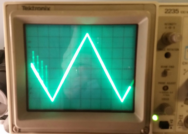
The PWM frequency for the waveform shown was set at 64KHz. To catch the noise the easiest way I found was to generate an upward and downward ramps (sawtooth). To do this I use the clock module in TI-RTOS to generate calling a function at 8KHz. In the function I simply inc or dec a counter and use 'MatchSet' to alter the mark/space smoothly and so generate the sawtooth waveform. (The code has a lot of excess baggage but it would be possible to minimise it if really necessary.) What's interesting is that the noise often (but not always) appears as a group of 4 spikes and is always on the same slope. Increasing the PWM frequency to 250KHz and above reduces the noise significantly however of course I lose bit depth and can only do this for 8-bit.

Have you in TI tried to generate analog out from PWM and have you seen similar behaviour. Do you think the source would be RF coupling, power lines or other and would you have any suggestions to minimise this ?

Is there a way (h/w or s/w) to easily switch off the RF transmission to see if the noise disappears.

Thanks for your support. Any suggestions welcome.

regards,

Stuart

Edinburgh. UK.

  • Hi Stuart,

    A few suggestions for debugging:

    1. You can easily turn off the RF on the CC3200 by simply never calling sl_Start() in your code.
    2. Capture just the PWM waveform output and look for any glitches or unexpected behavior.
    3. This may or may not be affecting your setup, but I would suggest repeating your test with the CC3200 timers instead of TI-RTOS. There is a PWM example in the SDK that you can utilize. This will give a better idea if the issue is hardware or software based.

    Best regards,
    Sarah
  • Hi Sarah,

    Many thanks for your prompt support. Feedback below.

    1. You can easily turn off the RF on the CC3200 by simply never calling sl_Start() in your code.

    Ans: Understood. In my application my tasks (including the one calling sl_start() are set to priority -1 so are never running. I only run the 8KHz clock module 'task' so it seems it's not RF interference.

     
    2. Capture just the PWM waveform output and look for any glitches or unexpected behaviour.

    Ans: mmm ... difficult to see any problem looking at the mark/space digital waveform (that's why I generate the ramps). Also I don't have a digital scope or logic analyser available to me at this time :(


    3. This may or may not be affecting your setup, but I would suggest repeating your test with the CC3200 timers instead of TI-RTOS. There is a PWM example in the SDK that you can utilize. This will give a better idea if the issue is hardware or software based.

    Ans: OK, have taken the PWM example from the SDK and modified it to simulate my application. In short I just use one timer for the YELLOW LED and comment out the others. I then use 1250 as the reload value to simulate 64KHz PWM. The UtilsDelay in main() I shorten to get all running quicker so I can generate a ramp using the iLoop count value directly(changed to int). I'll attach the code. Unfortuantely I'm still seeing the spikes (see attached sdk_pwm_example.jpg) so it doesn't seem to be related to TI-RTOS.

    My thoughts

    1. Can you confirm that when 'MatchSet' is called it does not load the new PWM value instantly but rather waits for the next reload point. If it loads instantly this may cause glitches however this would be a very non standard way of handling PWM so I'm doubtful this is the case. (By the way I've also previously used the PWM api with same results).

    2. What is actually running in the background when an application like 'PWM' is loaded and running. Is there something that can cause a global type interrupt or even disable interrupts at some low frequency ?

    3. Possible for you to replicate this ? Code is attached and h/w is very simple.

    best regards,

    Stuart

    PS. Not sure if you can pick up my 'main.c', let me know if I need to copy and paste it in.

    //*****************************************************************************
    //
    // Copyright (C) 2014 Texas Instruments Incorporated - http://www.ti.com/ 
    // 
    // 
    //  Redistribution and use in source and binary forms, with or without 
    //  modification, are permitted provided that the following conditions 
    //  are met:
    //
    //    Redistributions of source code must retain the above copyright 
    //    notice, this list of conditions and the following disclaimer.
    //
    //    Redistributions in binary form must reproduce the above copyright
    //    notice, this list of conditions and the following disclaimer in the 
    //    documentation and/or other materials provided with the   
    //    distribution.
    //
    //    Neither the name of Texas Instruments Incorporated nor the names of
    //    its contributors may be used to endorse or promote products derived
    //    from this software without specific prior written permission.
    //
    //  THIS SOFTWARE IS PROVIDED BY THE COPYRIGHT HOLDERS AND CONTRIBUTORS 
    //  "AS IS" AND ANY EXPRESS OR IMPLIED WARRANTIES, INCLUDING, BUT NOT 
    //  LIMITED TO, THE IMPLIED WARRANTIES OF MERCHANTABILITY AND FITNESS FOR
    //  A PARTICULAR PURPOSE ARE DISCLAIMED. IN NO EVENT SHALL THE COPYRIGHT 
    //  OWNER OR CONTRIBUTORS BE LIABLE FOR ANY DIRECT, INDIRECT, INCIDENTAL, 
    //  SPECIAL, EXEMPLARY, OR CONSEQUENTIAL DAMAGES (INCLUDING, BUT NOT 
    //  LIMITED TO, PROCUREMENT OF SUBSTITUTE GOODS OR SERVICES; LOSS OF USE,
    //  DATA, OR PROFITS; OR BUSINESS INTERRUPTION) HOWEVER CAUSED AND ON ANY
    //  THEORY OF LIABILITY, WHETHER IN CONTRACT, STRICT LIABILITY, OR TORT 
    //  (INCLUDING NEGLIGENCE OR OTHERWISE) ARISING IN ANY WAY OUT OF THE USE 
    //  OF THIS SOFTWARE, EVEN IF ADVISED OF THE POSSIBILITY OF SUCH DAMAGE.
    //
    //*****************************************************************************
    
    //*****************************************************************************
    //
    // Application Name     - PWM Application
    // Application Overview - The general purpose timers (GPTs) support a 16-bit 
    //                        pulse-width modulation (PWM) mode with software-
    //                        programmable output inversion of the PWM signal.
    //                        The brightness of the LEDs are varied from Off to On 
    //                        as PWM output varies.
    // Application Details  -
    // http://processors.wiki.ti.com/index.php/CC32xx_PWM
    // or
    // docs\examples\CC32xx_PWM.pdf
    //
    //*****************************************************************************
    
    //****************************************************************************
    //
    //! \addtogroup pwm
    //! @{
    //
    //****************************************************************************
    
    #include <stdio.h>
    
    // Driverlib includes
    #include "hw_types.h"
    #include "hw_ints.h"
    #include "hw_memmap.h"
    #include "hw_apps_rcm.h"
    #include "hw_common_reg.h"
    #include "interrupt.h"
    #include "rom.h"
    #include "rom_map.h"
    #include "timer.h"
    #include "utils.h"
    #include "prcm.h"
    
    #include "pinmux.h"
    
    #define APPLICATION_VERSION     "1.1.1"
    #define DBG_PRINT               Report
    //
    // The PWM works based on the following settings:
    //     Timer reload interval -> determines the time period of one cycle
    //     Timer match value -> determines the duty cycle 
    //                          range [0, timer reload interval]
    // The computation of the timer reload interval and dutycycle granularity
    // is as described below:
    // Timer tick frequency = 80 Mhz = 80000000 cycles/sec
    // For a time period of 0.5 ms, 
    //      Timer reload interval = 80000000/2000 = 40000 cycles
    // To support steps of duty cycle update from [0, 255]
    //      duty cycle granularity = ceil(40000/255) = 157
    // Based on duty cycle granularity,
    //      New Timer reload interval = 255*157 = 40035
    //      New time period = 0.5004375 ms
    //      Timer match value = (update[0, 255] * duty cycle granularity)
    //
    // #define TIMER_INTERVAL_RELOAD   40035 /* =(255*157) */
    #define TIMER_INTERVAL_RELOAD   1250 /* */
    #define DUTYCYCLE_GRANULARITY   157
    
    
    //*****************************************************************************
    //                 GLOBAL VARIABLES -- Start
    //*****************************************************************************
    #if defined(ccs)
    extern void (* const g_pfnVectors[])(void);
    #endif
    #if defined(ewarm)
    extern uVectorEntry __vector_table;
    #endif
    //*****************************************************************************
    //                 GLOBAL VARIABLES -- End
    //*****************************************************************************


    /****************************************************************************/
    /*                      LOCAL FUNCTION DEFINITIONS                          */
    /****************************************************************************/
    
    //****************************************************************************
    //
    //! Update the dutycycle of the PWM timer
    //!
    //! \param ulBase is the base address of the timer to be configured
    //! \param ulTimer is the timer to be setup (TIMER_A or  TIMER_B)
    //! \param ucLevel translates to duty cycle settings (0:255)
    //! 
    //! This function  
    //!    1. The specified timer is setup to operate as PWM
    //!
    //! \return None.
    //
    //****************************************************************************
    void UpdateDutyCycle(unsigned long ulBase, unsigned long ulTimer,
                         unsigned int ucLevel)
    {
        //
        // Match value is updated to reflect the new dutycycle settings
        //
    //    MAP_TimerMatchSet(ulBase,ulTimer,(ucLevel*DUTYCYCLE_GRANULARITY));
        MAP_TimerMatchSet(ulBase,ulTimer,ucLevel);
    }
    
    //****************************************************************************
    //
    //! Setup the timer in PWM mode
    //!
    //! \param ulBase is the base address of the timer to be configured
    //! \param ulTimer is the timer to be setup (TIMER_A or  TIMER_B)
    //! \param ulConfig is the timer configuration setting
    //! \param ucInvert is to select the inversion of the output
    //! 
    //! This function  
    //!    1. The specified timer is setup to operate as PWM
    //!
    //! \return None.
    //
    //****************************************************************************
    void SetupTimerPWMMode(unsigned long ulBase, unsigned long ulTimer,
                           unsigned long ulConfig, unsigned char ucInvert)
    {
        //
        // Set GPT - Configured Timer in PWM mode.
        //
        MAP_TimerConfigure(ulBase,ulConfig);
        MAP_TimerPrescaleSet(ulBase,ulTimer,0);
        
        //
        // Inverting the timer output if required
        //
        MAP_TimerControlLevel(ulBase,ulTimer,ucInvert);
        
        //
        // Load value set to ~0.5 ms time period
        //
        MAP_TimerLoadSet(ulBase,ulTimer,TIMER_INTERVAL_RELOAD);
        
        //
        // Match value set so as to output level 0
        //
        MAP_TimerMatchSet(ulBase,ulTimer,TIMER_INTERVAL_RELOAD);
    
    }
    
    //****************************************************************************
    //
    //! Sets up the identified timers as PWM to drive the peripherals
    //!
    //! \param none
    //! 
    //! This function sets up the folowing 
    //!    1. TIMERA2 (TIMER B) as RED of RGB light
    //!    2. TIMERA3 (TIMER B) as YELLOW of RGB light
    //!    3. TIMERA3 (TIMER A) as GREEN of RGB light
    //!
    //! \return None.
    //
    //****************************************************************************
    void InitPWMModules()
    {
        //
        // Initialization of timers to generate PWM output
        //
        MAP_PRCMPeripheralClkEnable(PRCM_TIMERA2, PRCM_RUN_MODE_CLK);
        MAP_PRCMPeripheralClkEnable(PRCM_TIMERA3, PRCM_RUN_MODE_CLK);
    
        //
        // TIMERA2 (TIMER B) as RED of RGB light. GPIO 9 --> PWM_5
        //
    //    SetupTimerPWMMode(TIMERA2_BASE, TIMER_B,
    //            (TIMER_CFG_SPLIT_PAIR | TIMER_CFG_B_PWM), 1);
        //
        // TIMERA3 (TIMER A) as YELLOW of RGB light. GPIO 10 --> PWM_6
        //
        SetupTimerPWMMode(TIMERA3_BASE, TIMER_A, 
                (TIMER_CFG_SPLIT_PAIR | TIMER_CFG_A_PWM | TIMER_CFG_B_PWM), 1);
        //
        // TIMERA3 (TIMER B) as GREEN of RGB light. GPIO 11 --> PWM_7
        //
    //    SetupTimerPWMMode(TIMERA3_BASE, TIMER_B,
    //            (TIMER_CFG_SPLIT_PAIR | TIMER_CFG_A_PWM | TIMER_CFG_B_PWM), 1);
    
    //    MAP_TimerEnable(TIMERA2_BASE,TIMER_B);  // RED
        MAP_TimerEnable(TIMERA3_BASE,TIMER_A);  // YELLOW
    //    MAP_TimerEnable(TIMERA3_BASE,TIMER_B);  // GREEN
    }
    
    //****************************************************************************
    //
    //! Disables the timer PWMs
    //!
    //! \param none
    //! 
    //! This function disables the timers used
    //!
    //! \return None.
    //
    //****************************************************************************
    void DeInitPWMModules()
    {
        //
        // Disable the peripherals
        //
        MAP_TimerDisable(TIMERA2_BASE, TIMER_B);
        MAP_TimerDisable(TIMERA3_BASE, TIMER_A);
        MAP_TimerDisable(TIMERA3_BASE, TIMER_B);
        MAP_PRCMPeripheralClkDisable(PRCM_TIMERA2, PRCM_RUN_MODE_CLK);
        MAP_PRCMPeripheralClkDisable(PRCM_TIMERA3, PRCM_RUN_MODE_CLK);
    }
    
    //*****************************************************************************
    //
    //! Board Initialization & Configuration
    //!
    //! \param  None
    //!
    //! \return None
    //
    //*****************************************************************************
    static void
    BoardInit(void)
    {
    /* In case of TI-RTOS vector table is initialize by OS itself */
    #ifndef USE_TIRTOS
      //
      // Set vector table base
      //
    #if defined(ccs)
        MAP_IntVTableBaseSet((unsigned long)&g_pfnVectors[0]);
    #endif
    #if defined(ewarm)
        MAP_IntVTableBaseSet((unsigned long)&__vector_table);
    #endif
    #endif
        //
        // Enable Processor
        //
        MAP_IntMasterEnable();
        MAP_IntEnable(FAULT_SYSTICK);
    
        PRCMCC3200MCUInit();
    }
    
    //****************************************************************************
    //
    //! Demonstrates the controlling of LED brightness using PWM
    //!
    //! \param none
    //! 
    //! This function  
    //!    1. Pinmux the GPIOs that drive LEDs to PWM mode.
    //!    2. Initializes the timer as PWM.
    //!    3. Loops to continuously change the PWM value and hence brightness 
    //!       of LEDs.
    //!
    //! \return None.
    //
    //****************************************************************************
    void main()
    {
        int iLoopCnt;
    
        //
        // Board Initialisation
        //
        BoardInit();
        
        //
        // Configure the pinmux settings for the peripherals exercised
        //
        PinMuxConfig();    
        
        //
        // Initialize the PWMs used for driving the LEDs
        //
        InitPWMModules();
    
        while(1)
        {
            //
            // RYB - Update the duty cycle of the corresponding timers.
            // This changes the brightness of the LEDs appropriately.
            // The timers used are as per LP schematics.
            //
            for(iLoopCnt = 50; iLoopCnt < 1200; iLoopCnt++)
            {
    //            UpdateDutyCycle(TIMERA2_BASE, TIMER_B, iLoopCnt);        // RED
    //            UpdateDutyCycle(TIMERA3_BASE, TIMER_B, iLoopCnt);        // GREEN
                UpdateDutyCycle(TIMERA3_BASE, TIMER_A, iLoopCnt);          // YELLOW
    //            MAP_UtilsDelay(800000);
                MAP_UtilsDelay(80);
            }
          
        }
    
        //
        // De-Init peripherals - will not reach here...
        //
        //DeInitPWMModules();
    }
    
    //*****************************************************************************
    //
    // Close the Doxygen group.
    //! @}
    //
    //*****************************************************************************
    

  • Hi Sarah,

    More info for you.

    When starting at max MARK and decreasing the MARK/SPACE ratio the downward ramp produced is ROCK SOLID.

    It's only when starting at min MARK and increasing the MARK/SPACE ratio for the upward ramp that I get the noise spikes.

    I'm not seeing any logical explanation for this other than the counter for some reason very occasionally not being loaded correctly.

    Have tried multiple Launchpads and different timers/pins.

    I've modified the code and I'm currently using PWM0 (pin21) with same result. The loop I use to generate the upward (noisy) ramp is below.

    while(1){

    UpdateDutyCycle(TIMERA1_BASE, TIMER_A, iLoopCnt);
    MAP_UtilsDelay(80);
    iLoopCnt = iLoopCnt+1;
    if (iLoopCnt == 1200) iLoopCnt = 50;

     }

    Any further thoughts on your side (perhaps with my earlier questions) ?

    best regards,

    Stuart

  • Hi Sarah,

    I was hoping you may have an update for me.

    Did you manage to replicate the issue (quite straightforward to do) ?

    thks & rgds,

    Stuart