Hi,
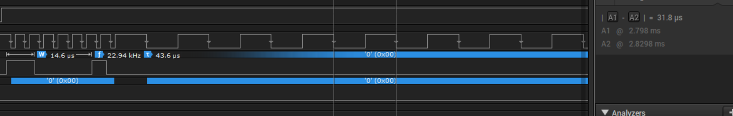
I have a peripheral which needs to change the SPI clock frequency after writing a command to it, the same is shown in the below figure.
Is there a simple way to do this with TI libraries?

Thank you,
Kishore.
Original question:

Hi,
I have a peripheral which needs to change the SPI clock frequency after writing a command to it, the same is shown in the below figure.
Is there a simple way to do this with TI libraries?
Thank you,
Kishore.