This thread has been locked.

If you have a related question, please click the "Ask a related question" button in the top right corner. The newly created question will be automatically linked to this question.

CCS/CC3120BOOST: CC3120 BOOST and Uniflash

Part Number: CC3120BOOST
Other Parts Discussed in Thread: UNIFLASH, CC31XXEMUBOOST, CC3120, CC3200, CC3100, SYSCONFIG, AMIC110, AM3359, SYSBIOS

Tool/software: Code Composer Studio

Hello all,

Despite the post claiming it's for CCS, it's actually for "Uniflash", but the E2E doesn't give me that option...

I am trying to learn the CC3120 device from the starting line.   So I purchased the CC3120 Boost, CC31XXEMUBOOST, and the MSP432P401R launchpad.

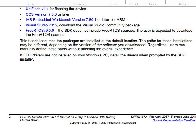
Then I consulted document SWRU467A  The start guide.

(Let me preemptively say, when people start asking "why did you install that component?? Why are you using that document?? What is wrong with you??"  It's because TI's web pages listed those docs for the devices I was looking for, and they don't explain anything comprehensively) 

As is typical of TI instructions and support, I can't get past the first step...  Bit's pretty much broken from the starting line.

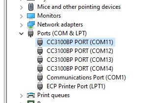
I know I installed the drivers during one of the 4 installations, because I see 4 COM ports when the EMU is plugged in.

Okay, so far....  Until....  The document tells me to use Uniflash 4.x...   

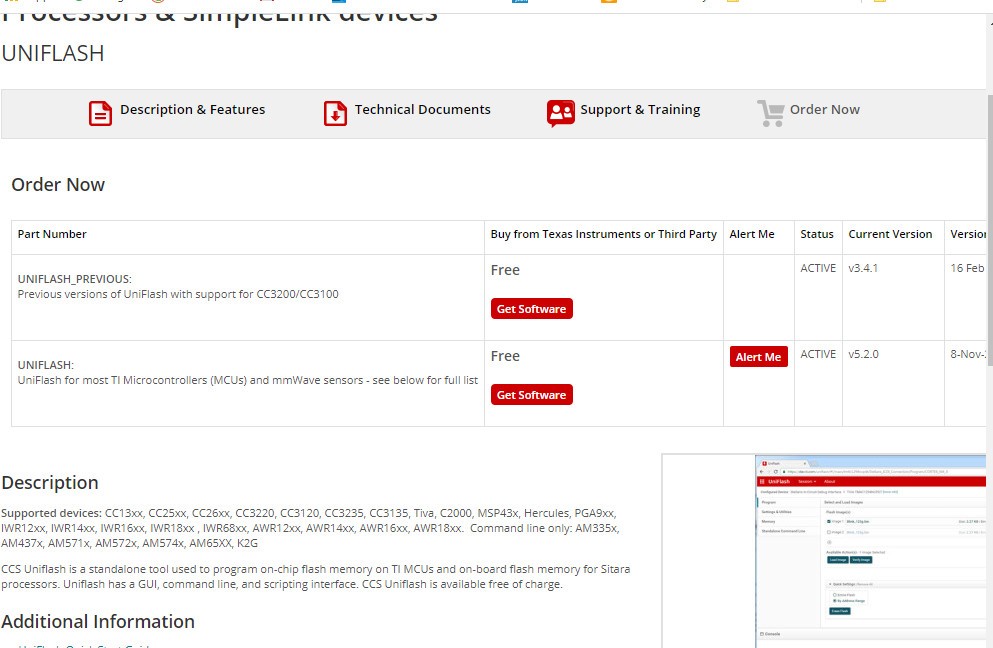
There isn't one.  There is 3.x and 5.x

What IS this tool anyway?   What does it do?  Why is it needed??  More questions that TI doesn't give any useful training.  Simply listing "supported devices" under "Description" isn't really very bright...

Version 5 says "see below".  And my device is listed as supported. But in version 5, when I press "detect"  it doesn't recognize my device.  It says Not found...

And version 3 UI is nothing like version 5, so the guide is useless for it.  Since I have no idea what the Uniflash app is supposed to do (besides install drivers for dozens of chipsets that I am not using), I have no idea what the settings on it are supposed to be.

I have installed the SDK's, and again, typical of TI, the tutorials tells me to look into SDK folders that do not exist.

So my question:  Would someone please be kind enough to point me to the correct startup material that actually matches the tools and software TI publishes?

  • Hi,

    As first thing I want to say. As a independent developer and E2E forum user with more than 5000 posts I need to say that I never seen answers like "why did you install that component?? Why are you using that document?? What is wrong with you??" at E2E forum. I think your post is not fair to hundred of TI employees and other E2E members which are helping with problems of other user.

    As extensive resource of information about CC32xx/CC1xx device you can use TI Resource Explorer and SimpleLink Academy.

    Jan

  • Hi Chris,

    I apologize for any confusion based on the documentation you found. I'll go look at that and make sure we can update it. For CC3120, you will definitely want to use the UniFlash 5.x and NOT UniFlash 3.

    The guide that my team maintains (it needs to be updated followinging the v3.40.00.05 release that just happened last night) is this one and I believe it is much simpler for getting started. Note that it references 4.6 or later:

    http://dev.ti.com/tirex/explore/node?node=ABEoqU9o3snoxDcmIpW0EA__fc2e6sr__LATEST

    Best Regards,

    Ben M

  • Thanks for your quick reply.

    I have received valuable assistance from others. It was a preemptive defense against the "why aren't you looking where you are supposed to?" flames.

    On those occasions I can connect to a actual TI employee, they are generally very helpful.

    You  missed some of the posts that have insulted me for not having some "in-bred" knowledge of the environment, or software libraries, or device choices, etc.  Or for having the audacity to ask a question without going out and finding the answer already, from other sources.

    So, aside from that, lets follow these links  (which, by the way, are not linked to from any of the device pages when I was selecting the 3120Boost board, the BootEMU board, or the MSP432 board...  There were, however, at least 12 PDFs and 6 executable installs which I downloaded and attempted to use - because it doesn't explain what I need, what it does, or if it overlaps with many other packages)

    Following the link from SimpleLink SDK plugings | Connectivity | SimpleLink DSK Wifi Plugin | 2.40 | SimpleLink Academy | Overview  Task 1 : Setting up the hardware,  it states  "please see the UniFlash ImageCreator Basics SimpleLink Academy."

    That takes me to a page titled UniFlash ImageCreator Basics

    That says (and has a link to) "This lecture only covers version 4.6.0 or later of UniFlash."

    Which takes me back to the download page where is says version 3 or version 5

    Which I already said doesn't seem to work.  On version 5, the TOP GUI are says no devices detected, even while it is plugged in and enumerate COM ports.  The BOTTOM GUI area doesn't even have my CC3120BOOSTEMU listed as an option.

    So I'm back to where I was regarding that PDF SWRU467 which I downloaded from the device page.

    I'll read into "The Academy" material.  And see if it sheds any light...

  • Ben,

    Thanks for this link...   This threads from the link that Jan posted.  So I will "start over" reading that material.

    If this "Resource Explorer" and "Academy" material is the primary tutorials and examples, perhaps all those other PDFs on the device pages should be taken down since they have (at least in my experience dealing with Sitara and Tiva) old, inaccurate material that simply steered me into the stands.

    And links to these Resource pages be put up instead.

    Look as some of these documents (just user guides)  and software packages being people told to review and install on these pages:
    https://www.ti.com/tool/CC3120BOOST

    https://www.ti.com/tool/CC31XXEMUBOOST

    https://www.ti.com/tool/MSP-EXP432P401R

    You know... One of those pages ended up telling me to install something that created "C:\ti\CC3100_CC3200_ServicePack_1.0.1.11-2.10.0.0"...  But there is no "service pack" in there.  Apparently the "service pack" is over in C:\ti\simplelink_sdk_wifi_plugin_2_40_00_22\tools\cc31xx_tools\servicepack-cc3x20

    This is very confusing and frustrating to a new person who doesn't know the vernacular. 

  • Hello Ben,

    I have a simple question:

    About the document  CC3x20, CC3x35 SimpleLink™ Wi-Fi  and  Internet of Things Network Processor  Programmer's Guide

    AKA document  SWRU455

    Is this document still correct and current?

    Specifically, chapter 19 which is "Porting the Host Driver".

    It has been my experience, and your comment about "confusion on documents" reinforces it, that a plethora of material is just left out there for us to stumble across and waste hours or even days, before we realize that is it deprecated.

    My goal is to port the driver and API to work with a Sitara AM 335x MCU.  (I have already successfully converted a MicroChip/Atmel driver to communicate with one of their devices, however I discovered a defect/deficiency so now I intend to evaluate the CC3120)

    UPDATE:  I'm going to answer this and say "NO".   Because as I dig through this, and attempt to examine example project, I see a function in the examples called "sl_WifiConfig()".  This function is NOT documented ANYWHERE in the above mentioned programming guide.  And yet, it appears to be required, has a comment in the example source module that states:

    /* IMPORTANT NOTE - This is an example reset function,
             user must update this function to match the application settings. */

    However, it is burried deep in the driver code, NOT where a user can find it, and lastly is bereft of any explanation.

    So, where IS current documentation that is comprehensive?

    Thanks.

  • Hi Chris,

    Yes, SWRU455 is current though we are always working to improve it. The sl_WifiConfig() function is a bit special because it is not strictly necessary to use the host driver. Most of the host driver is implemented such that functional calls will build commands based on opcodes and parameters in order to send them to the network processor. That function just calls other host driver functions to give a "default configuration" based on the outputs of the Sysconfig UI.

    That note is intended to convey that sl_WifiConfig() is just a reference for "resetting" the device state to some default configuration and would, most likely, be replaced by a function in your own application which configures the device to a default state.

    Can you describe the issue you are running into with that function and porting the host driver?

    My guess would be that you are running into an unresolved symbol due to missing the definition for:

    const SlWifiCC32XXConfig_t SimpleLinkWifiCC32XX_config

    If you look at our examples, that constant is just a struct with default values that get passed to other SL function calls in the sl_WifiConfig() function. Including this in your project should resolve the issue or you can remove the sl_WifiConfig() function completely.

    I'm not sure what your overall goal is relating to using the AM335 device as a host, but I would recommend you take a look at the port that was done a while ago for the AMIC110 -

    https://e2e.ti.com/support/processors/f/791/p/690896/2547179#2547179

    Given that this isn't a typical host platform, it's not a release that our team maintains. If you're developing with the AM335, I would recommend taking a look at our WiLink products. 

    http://www.ti.com/wireless-connectivity/simplelink-solutions/wi-fi/overview/wilink-combo-solutions.html

    Best Regards,

    Ben M

  • Ben,

    Thanks for the advice.

    First off, the WL18xx series looks interesting, but there isn't anything I see about TI-RTOS driver.  Nowhere did it mention if the TCP/IP stack in built in.  I assume it isn't, because at 100 Mbs, it's not likely running through SPI bus.  It more likely has to integrate directly into the NDK NIMU and uses DMA.

    I'm not sure how to prototype that at this time.

    Thanks for telling me what the sl_WifiConfig() is for.  Since I had to actually go online and ask in a forum, stumbling across a TI guy who could tell me.  Because nowhere else did I see it tell me "That is something you won't use".

    Back to the CC3120...  I did already see that AMIC110 thread last week. The discussion was about the SPI, which I've already solved when I had this integrated to a different module.  I didn't see anything in their discussions about integrating the HWI.  And the files in that post are just the macros to replace the kernel objects, as the document describes. Logically, I intend to use the SYS/BIOS API...  I started down that path, and walked away due to lack of information of how to actually BUILD it

    What is NOT explained in that post is WHICH of the 100+ source files need to be used in the rebuild.  Nor HOW to actually rebuild the SDK.  (the "processor_sdk_rtos_am335x" actually has a script that is used to build it, and instructions...  it fails, and someone once replied "Yeah, well, we know..."  But at least there were instructions).

    No script or instructions are found for this.

    If I want to use the SYS/BIOS semaphores and GateMutexes, I have no clue how to build it in a script anyway.  Nothing that uses the SYS/BIOS ecosystem can be built outside of CCS without obtaining some kind of PhD in the environment.  The CFG file generates some JAVA code that in turn generates tons of C code, other cmd files, make files, etc... I have no idea which tool it invokes to do that.  There is no instruction on accomplishing this in any other way but the IDE, so I am forced to do it inside CCS.

    When I tried the first time just dragging everything in, I uncovered dozens of header conflicts.  (You know, there is already a header named errno.h...  adding another one to the simplelink SDK creates all kinds of issues)

    What I am doing now is unraveling the "network terminal" project to see which archive libs it links to.  Then digging into the buried makefile defs to determine the source files which (I think) were used to create each archive file.  Then manually creating projects in CCS so I can also import the SYS/BIOS kernel objects into my own archive modules build for the AM335x device.  Then I will link my test project to those libs.

    The above information could easily be placed in a single document saying "here is a list of the lib names, here is a list of the functions in them, and here is a list of the source files that are used to make them".  Why TI never thinks of providing such fundamental information is beyond me.

    It's slow progress, but at least it's progress.  Not like the week I wasted digging through 1000's of pages of doc only to learn it's NOT telling me what I need to know after chasing PDFs and hyperlinks down dozens of dead end holes.

    Can you hear my frustration??

  • Hi Chris,

    I understand the challenge you are working through. To be clear, we do not support the configuration you are trying to use, AM335x + CC3120 with TI-RTOS, in software today. It is not a configuration that we typically see customers use and we have no plans to release collateral specific to that. This is the biggest reason you are running into headaches.

    That being said, we are happy to help guide you on any specific questions you have. I just can't guarantee this is something that will be easy or straightforward to pull off because the software we provide is not designed to enable it by default. 

    At this point, I'm struggling to figure out what answers you are looking for. Please let us know what help you need. If you can provide a general description of the requirements for your system, we can try to recommend an easier solution.

    Best Regards,

    Ben M

  • Hi Ben,

    Thanks for your reply. Inconvenient timing, as I am about to got on vacation for a week.

    My silence over the next weeks would not be lack of caring or needing support....  Just taking a break. 

    Anyway, I am more than happy to do the porting myself. I ported a USB driver, wrapped an RNDIS protocol in it, and merged it to the NIMU component of the network stack.  All of these were dealing with TI driver software that was NOT documented at the lower level I was dealing with.  (TI  documentation is always how to use the driver function, not how it works so nothing explains how it can be adapted to other peoples needs.) I reverse engineer it myself (using a lot of paper drawings and documenting).

    As another point of reference, I ported the driver used by an ATMEL WINC1500 device over the the am335x.  I handled the SPI communication, ISRs, etc. It is working fine from the host MCU point of view.  ( I would be using that device if not for a defect I found in the firmware, and can't get their first level support to understand the issue.)  The design of that one seems to be the similar to the CC3120:  SPI packets, Interrupt when something needs servicing, callback for types of events read out of the device, etc...  The ATMEL driver was documented, so it was easier to understand.  And convert.

    I am trying to do the same here, and have tried to replace the necessary calls with SYS/BIOS equivalents, as well has semaphores and critical sections.  Now, as of a day ago, it finally builds.  But gives me a timeout.  I will dig in to see if that is due to an interrupt not occurring when expected, or a SPI reply not being read back, or whichever interprocess lock is not being released.

    An architectural overview of this driver would be useful.  I am not referring to doc about how to use the driver, but how the communication flows, and the modules interact. Unraveling has been difficult, especially since there are function names that are #defined to other function name which are then #defined to yet others  (a nasty habit XDC has been doing as well)  First thing I notice is that all the tasks are now "pthreads" rather than SYS/BIOS tasks (which "Task_create()" is not specific to the Sitara device, it is supposed to work on all the lines... until I had to deal with the MSP432...  why??).  So those function signatures are all different.  It appears the interrupt launches another "task" with every event...?  Naturally I would worry about memory fragmentation, etc..  I would rather redesign it to have a paused task which is released when the ISR signals that it has something which needs to be done.  But I have no architecture of the driver to take on such an effort yet.

    The example has a function which is in the driver lib which is not documented.  I found that particularly annoying...  Since I now have to grep it and reverse engineer it to see what it does.

    At this stage, I am will want to use the built in TCP/IP stack. We need to have an HTTPS server, which handles complex AJAX posts. Eventually, I suspect I could tie the low level packets into the NIMU, moving the upper stack processing into the host MCU.  But that means an understanding of the details of the WiFi level contents, and configuring the unit to communicate at that lower OSI level of 2 or 3, rather than OSI layer 5  (if that makes sense).

    Let me know if you understand what I am looking for, if you can provide the necessary information, or even if there is someone that can be contracted to assist and transfer this knowledge.

  • Hi Chris,

    I'll take that feedback to the team as we plan new documentation and updates. I agree that we can do a better job documenting the driver in a way that makes it easier to understand the necessary steps for porting to new devices. I agree that some description of the overall architecture may help here.

    In regards to the statement - "it appears that the interrupt launches another "task" with every event...?"

    Are you referring to the sl_Spawn() call inside the _SlDrvRxIrqHandler()? There is an option to attach this to an os_Spawn() call, but that shouldn't be what we do in our SDK by default. I believe our internal spawn mechanism that is used by default is waiting on a semaphore and then doing work as signaled. Refer to the spawn.c file.

    There is always the option of bypassing the TCP/IP stack once you have the driver up and running as you have mentioned. We document the options here in sections 6.5.3/6.5.4 of the network processor programmers guide.

    Best Regards,

    Ben M

  • Ben,

    Benjamin Moore said:
    I agree that some description of the overall architecture may help here.

    Yes, can someone provide it?  Even a photo of a cocktail napkin?  :-)

    Benjamin Moore said:
    Are you referring to the sl_Spawn() call inside the _SlDrvRxIrqHandler()?

    Yes,   Line 805 says

    if (TRUE == g_pCB->WaitForCmdResp)
        {
            OSI_RET_OK_CHECK(sl_SyncObjSignalFromIRQ(&g_pCB->CmdSyncObj));
        }
    ...

    Which indicates... what?  That this is a 100% blocking call from the point of view of the calling app?  And the calling app can put this in it's own task?

    Or this is intended to be single threaded, not using a task based RTOS?

    What is "WaitForCmdResp" variable?  Who sets it?  And how?   I could spend days reversing the code (which I am doing) but a little help with the internals being documented would be appreciated.

    So, as I try to determine which way to trace the code, I don't know which is happening.

    Benjamin Moore said:
    We document the options here in sections 6.5.3/6.5.4 of the network processor programmers guide.

    Well, as for this, it's just another broken thing from TI, which I have come to expect.

    I figure it's the current "swru455i" version of the doc, as surmised from the URL.  I've got that doc, and was referring to it.  But it doesn't describe the internals, and Sarah P (on another thread) said that the porting section will be removed from the doc...  and I should just rely on the Doxygen (which I despise).

    I intend to use section 6.5 to bypass the stack, once I get the driver working.  But first I need to know it is functioning after I ported ti.  Until than I'm not even sure anything is correct...  Gotta crawl before I can even walk on this environment.

    if(TRUE == g_pCB->WaitForCmdResp)    {        OSI_RET_OK_CHECK(sl_SyncObjSignalFromIRQ(&g_pCB->CmdSyncObj));    }

  • Ben,

    (Or anyone else willing to support TI customers)

    Is there any hope of sourcing documentation the internals of this driver?

    Currently, all I can see is that the "sl_Start" lowers the hibernate pin (active low), than raises it, and goes to sleep waiting for something, somewhere, to somehow, signal an event in the "zeroth" sync object (because it's the first one used after initializing everything).

    But there is no way to determine what is supposed to signal that event...  An interrupt?  Another thread or task?

    So many things are #defined to some other piece of text, that is then #defined to yet ANOTHER piece of text, it's a headache to ultimately figure out what is talking to what.

  • Hi Chris,

    We don't have a full description of the driver that we can share externally at this point. This is something I will work with the team on planning to provide in the future.

    We can definitely help walk you through the behavior you should be seeing and debug issues you are running into if you can help us understand where your system is stuck/running into errors.

    Regarding the initialization of the host interface and powering up the network processor, this is page describes it pretty well -

    https://processors.wiki.ti.com/index.php/CC3100_Host_Interface

    It was written for the CC3100 and still generally applies for the CC3120. Just FYI, this specific documentation is part of what we are working on updating and moving into existing documentation on ti.com this year.

    The other key part of sl_Start is that it calls the interrupt handler register function that is provided by the application. That allows the host driver to register the internal _SlDrvRxIrqHandler(). That handler should be triggered by the host IRQ pin from the CC3120. When the network processor is pulled out of hibernate (on sl_Start), it will signal that the HW/FW initialization is done by asserting the IRQ pin. That will trigger the interrupt handler and cause the host to read back the status (which includes information like device role) and then unblock sl_Start() through the async event.

    Best Regards,

    Ben M

  • Benjamin Moore said:

    The other key part of sl_Start is that it calls the interrupt handler register function that is provided by the application. That allows the host driver to register the internal _SlDrvRxIrqHandler(). That handler should be triggered by the host IRQ pin from the CC3120. When the network processor is pulled out of hibernate (on sl_Start), it will signal that the HW/FW initialization is done by asserting the IRQ pin. That will trigger the interrupt handler and cause the host to read back the status (which includes information like device role) and then unblock sl_Start() through the async event.

    Ben,

    This helps...  I kind of suspected that an IRQ would trigger, but could not validate that is what Device.c, line #184 was waiting for

                VERIFY_RET_OK(_SlDrvWaitForInternalAsyncEvent(ObjIdx,
                                 INIT_COMPLETE_TIMEOUT,
                                 SL_OPCODE_DEVICE_INITCOMPLETE));
    

    I can re-verify my jumpers and check for activity on those lines with my scope/counter (I'm not above assuming my prototype wiring could have a flaw)

    However...

    My hand tracing indicates the ISR signals the g_SlInternalSpawnCB.SyncObj, (of which there is only one)  although the wait in Device.c is being passed an index of a semaphore in the collection inside g_CB.ObjPool[ ... ] .  So I can't yet see how these connect.

    (By the way, not wanting to be to picky, the timing diagram shows 8 cycles of hibernate at 32Khz.  Which is 250us if I did the math right...  This doc says the hibernate must be low for 10ms.)

  • Hi Chris,

    There are two cases in the IRQ handler:

    1) If the host driver is blocking in the middle of a command waiting on a command response

    2) The host driver is not blocked on a command and needs to handle an asynchronous event

    In the latter case where sl_Spawn() is called and signals the g_SlInternalSpawnCB.SyncObj, that unblocks the spawn thread (sl_Task()...which maps to _SlTaskEntry and therefore _SlInternalSpawnTaskEntry by default) and allows it to run to handle the asynchronous event.

    sl_Task should already have been created in the system before sl_Start() was called. It will be blocked in _SlInternalSpawnWaitForEvent() before the IRQ handler. Once triggered by the handler, it will  run _SlDrvMsgReadSpawnCtx() to retrieve the message from the network processor, classify the message type, and then use _SlDrvAsyncEventGenericHandler() to signal the semaphore that sl_Start() was actually blocked on.

    Best Regards,

    Ben M

  • Ben,

    Okay, I found a crossed signal, and have the interrupt triggering.  And the semaphores and locking mutexes appear to be working as designed.

    I have TWO issues now, although they are likely related.   Should I continue to discuss it with you on this forum, or open a new thread post, or try to find some direct help?

    1. When sl_Start(...) is executed, I get a 

    [ERROR] - FATAL ERROR: Sync loss detected

    but when I step through the code, I don't get that error.  It seems like some kind of timing thing, but I see a loop where it tries to ready a a message on the SPI bus until it finds the correct message.   So stepping through the code slowly finds the message.  (The 500Mhz+  am335x is faster than the driver expects?)

    2.  If I step through to get past the sl_Start(...) function, then attempt to issue a "sl_WlanDisconnect()", it times out and gives me 

    [ERROR] - FATAL ERROR: No Cmd Ack detected [cmd opcode = 0x8c81]
    Network LAN ERROR: -2005

    Any suggestions on where to begin troubleshooting this?  Can you point me to which document would be a good reference to diagnose this SPI communication?

  • Ben,  (or anyone else)

    Is there any support on the internals of the CC3120 SPI communication?

    Way down in the guts of Driver.c, there is a function called _SlDrvRxHdrRead(...) it appears to send four bytes of H2N_SYNC_PATTERN to the device {0xBBDDEEFF,0x4321,0x34,0x12}.

    Then it tries to read 8 bytes back, and keeps trying until the first four bytes are NOT the same as the second four bytes.

    Then it goes on some obscure hunt for a "sync pattern" which is a macro, inside a macro, inside a macro... so it's an obfuscated mess trying to understand.

    What I do see is that coming out of Hibernate, the module is signalling an interrupt.  But the attempt to read the interrupt reason usually gives simply 0xFFFFFFF...  unless I pause and step through the code.  Then the module is actually sending stuff on the SPI bus.

    Are there some timing requirements after the interrupt?  What other possible reason would the module NOT be replying  (not asserting the MISO line)?

    Is there a requirement about the SPI-CS line needing to remain asserted?

    Is there any documentation on this synchronization?   The CC3100 doc doesn't give details, and also specified sync packets that are different from this driver.

  • Hi Chris,

    Yes we can/should continue to discuss this on the forum. I may loop in others from the team to help look at this too.

    One quick question -> did you implement the slcb_GetTimestamp function in your application and connect it to the host driver in your user.h file? If so, what is the frequency of the tick?

    By default, the host driver should assume that the tick value is in milliseconds. It then uses a couple defines in driver.h to set "short" and "long" timeout values for different API calls to the network processor. The "short" timeout value is 10 seconds and the "long" is ~65 seconds. They are much higher than the actual time it takes for operations to complete when comms are reliable. The INIT_COMPLETE_TIMEOUT should be the long timeout.

    It sounds like while the host driver is trying to read the SYNC pattern from the network processor, it is timing out and returning SL_API_ABORTED in the _SlDrvRxHdrRead() function. That will cause the host driver to call the _SlDrvHandleFatalError() function because the host driver assumes that the devices are out of sync and unable to correctly exchange data/messages.

    There isn't a document specifying the exact timing requirement because the driver is intended to be very generous in terms of timeouts. That makes me think there is just a mismatch in how the host driver is interpreting the tick value and it's not actually using 10 or 65 second timeouts.

    Best Regards,

    Ben M

  • Ben,

    The device I am running is the am3359 BeagleBone, at 500 Mhz.  And the SPI clock is set to 12 Mhz.  

    (I am successfully communicating with another vendors module using the same design of SPI, ISR, events...   And it works as expected, so I am confident in the code that handles the GPIO, ISR, and SPI lines)

    Yes, it is doing as you describe.  

    Within the _SlDrvRxHdrRead call, it is checking _SlDrvIsTimeoutExpired.   That is counting down "10_MILLISECOND" ticks.  That is mapped from the SYSBIOS "TimerGetCurrentTimestamp" funciton.  It returns an abort when the timeout occurs.

    (This is all SYSBIOS which drives me crazy trying to find useful doc. So I just do some performance tests on the calls.  It's actually FASTER for me to do that, then spend hours trying to find useful information.)

    I have to assume the driver code is solid, and the only issue is related to translating calls to be compatible with SYSBIOS/TI-RTOS.  And those are only semaphores, mutexes, timing, and threads.   And my tests seems to indicate they are working correctly.

    Example: I inserted a piece of test code before anything else, where I obtained the tick count, performed a a task_sleep(10) and checked again. Set a breakpoint and checked it...  The delta was 10 as expected.  Task sleep argument is 1 millisecond counts, and confirmed with a scope.

    Another example: I put a temporary infinite loop around the "NWP_IF_WRITE_CHECK()" call with a task_sleep(1) so I could scope it and confirm the following:

    • The SPI_CS0 line goes low
    • The SPI CLK line starts low then shows 4 clock bursts of bytes be sent.
    • The MOSI line shows data in sync with the clock pulses.
    • After completed, the SPI_CS0 line goes back high.
    • The process repeats about every1 ms.

    So this is as I would expect, because I only looped around the "write" porttion.

    Do I need pull ups on the MISO line?  I can find nothing in the doc that says if I should do that or not.

    I don't know if the SPI_CS0 line should remain low across the reads and writes...?  Our driver pulls it low when the write starts, and releases it after the specified number of bytes have completed being sent, then goes low to do a read.  And that worked with the other module.

    What I don't know is if the four bytes being send as "CNYS" are supposed to be reflected back as 8 bytes of "CNYS SYNC"...?

    Lastly... ONE TIME, when I was stepping through the code, and got past the stage, and released it to run...  I received a WIFI event and it told me it was connected to my SSID access point as expected (pre-configured using the web page in AP mode when I first got the module).  This tells me the module is working, and at some point it was capable of telling my host MCU that it's connected.

  • Ben,

    What is the timing supposed to be here?

    First of all, the _SlDrvRxHdrRead() call is not a window of 65 seconds.  It's only 50ms.  If it can't find the correct CNYS - SYNC packets, it fails.  The calls to _SlDrvStartMeasureTimeout() and _SlDrvIsTimeoutExpired() are a delta of 10ms, and will fail with an SL_API_ABORTED if it can't find the correct SYNC in that time.

    So I did some testing...

    When Hibernate is pulled low, then released, the IRQ line goes low about 10 ms later.

    And is stays low for about 75 ms!!

    All during that time, the IRQ has already triggered the "InternalSyncObject", and the _SlDrvRxHdrRead() begins trying to read.  It fails after 50ms, while the IRQ line is STILL low.  No wonder it's not getting any correct reads on the SPI line.

    My own logging and testing indicates:

    1. The device is removed from hibernate at 32ms,   
    2. Then the IRQ asserts at about 41ms  (add 75 to this, and that is the duration that the IRQ line remains low... to about 116ms). 
    3. It starts attempting to read the SYNC at about 63 ms (IRQ is still low).  It is getting nothing but 0xFFFFFFFF (because MISO is still floating high)
    4. At 115ms it reads the first non 0xFFFFFFFF as 0x00000000 , which passes some test as the read changed.
    5. It then goes into a "while(SearchSync && TimeoutState) { "   But the timeout has already pretty much been reached.
    6. At 127ms, it appears to decide that the 0x00000000 doesn't look like a SYNC and aborts.

    What is the IRQ trigger? Falling edge as I was using, or rising edge?    It is NOT documented anyplace I can find.  Either way, there will STILL be a 75ms pause between packets.  (doing some quick math, a 12Mhz SPI clock is 83ns per bit.  A 75 ms pause is about 900,000 bits worth of time, or 112K Bytes worth of delay.)

    I tried adding a 100ms delay to the beginning of _SlDrvRxHdrRead(...)  and finally did NOT get a timeout abort.  But adding 1/10 of a second to EVERY communication event is not acceptable.

    Is this the way it's supposed to be functioning? 

  • Hi Chris,

    You are correct about the 50 ms timeout on the header read. My apologies for the mistake.

    Why is your IRQ pin going low? It is an active high signal. This is documented in the pin attributes table of the datasheet. Also, the host should first write the "Host to device read" synchronization word before reading the "device to host" sync word from the network processor.

    http://www.ti.com/lit/ds/swas034/swas034.pdf

    The sequence should be along the lines of -

    1. nHib asserted to remove device from hibernate

    2. IRQ line goes high

    3. Chip select goes low (because it's active low) and host MCU clocks out the "Host to device read" pattern (CNYS) to network processor

    5. The host clocks out data from the network processor until it sees the "Device to host" sync word

    6. Then the host starts to read the opcode + length header of the payload

    The CS line may toggle between each read/write on the SPI interface.

  • Ben,

    The "Porting" chapter of swru455 did not specify the edge or level.  The HOST_INTR line is listed as "Active High".  And yet the line appears to remain high when "at rest" and after being released from hibernate (see my scope trace image). 

    Should the interrupt configuration be set to respond on Rising Edge or Level Detection?  The doc does not specify (and the existing source in the SimpleLink "cc_pal.c" module does not set the interrupt type either)

    The remaining steps you outline are all the same, as they have been executing the driver code unchanged except for my diag statements added.  So they are function as expected.

    By changing it to rising edge, I do get the correct SYNC-CNYS clocked in and out.  I have not gone deeper yet, as I just tested it.

    (Thanks for the info on the SPI_CS0 line. )

  • Hi Chris,

    The porting layer for the host driver allows the interrupt to be interpreted as either edge or level triggered. It is up to how you want to configure your host controller and the host driver. If you use level triggered, you need to implement the sl_IfMaskIntHndlr() and sl_IfUnMaskIntHdlr() - See the wiki under "The Host IRQ Line" section, https://processors.wiki.ti.com/index.php/CC3100_Host_Interface

    When you build your custom board, we do recommend you have a 100K pull-down on the hostIRQ line. See our hardware design checklist here:

    http://www.ti.com/lit/zip/swru462

    Best Regards,

    Ben M

  • Ben,

    I have accepted these replies as solutions, thanks for your help.

    An issue I have is now with performance.  I posted a new thread here:

    https://e2e.ti.com/support/wireless-connectivity/wifi/f/968/t/885876

    It is taking a full 1/4 second to read a few hundred bytes.  Sending is not taking a long time, so it's not the clock speed.

    I need to read byte by byte to find a delimiter before I can read the payload.  Is the single byte read being offloaded to through the SPI?  Is that the problem?

  • Hi Chris,

    Thanks for confirming. I'm glad you're up and running now.

    At a high-level, it seems like the performance issue relates to how the packets are buffered in the network processor, the protocol being used, and how the host is receiving byte-by-byte. I think we may need to clarify the transport protocol being used.

    A member of my team is going to look into the new E2E post and I'll make sure we follow-up as soon as possible.

    Best Regards,

    Ben M

  • Ben,
    And we're back to questions related to Uniflash...

    https://e2e.ti.com/support/wireless-connectivity/wifi/f/968/t/886310

    The other devices can connect to our EAP test box.  This environment is not clear, and generates more questions that answers.

    Any help getting one of the SME's on this topic to answer would be appreciated.

  • Chris,

    All of these are assigned directly to an individual on my team to be answered. Someone is already reviewing the question and will respond shortly.

    Best,

    Ben M