This thread has been locked.

If you have a related question, please click the "Ask a related question" button in the top right corner. The newly created question will be automatically linked to this question.

LAUNCHXL-CC3235S: Mismatch of pinmux generated on TI dev tool compare to hardware document

Part Number: LAUNCHXL-CC3235S
Other Parts Discussed in Thread: SYSCONFIG, CC3235SF, CC3235S, IWR6843

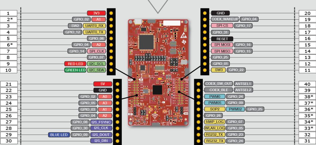
1. I entered pinmux tool on dev.ti.com. After I added UART and SPI, I saved those files to PC. I see some mismatch. As in hardware document of CC3235, UART RX is pin 3 on P1, UART TX is pin 4 on P1. But as the pinmux downloaded file sets them as pin 57 and 55, respectively. Why do I get this mismatch?

2. I looked at several sample codes in SimpleLink SDK (UARTCC32xx.c, uartecho.c, uartterm.c, uartpower.c...) but don't see any UART sample code declare pinmux settings. When do I need to declare pinmux settings in SimpleLink code?

Here's the pinmux list excel file I downloaded from dev.ti.com

  • Hi,

    1. CC3220 device have two UARTs which can be muxed to different pins by device settings. Please see schematic for your LaunchPad and datasheet for CC3235 (table 4-2) to learn capabilities of CC32xx devices.

    2. PinMux utility is obsolete at CC3220/CC3235 devices. It was replaced by Sysconfig configuration GUI inside CCS. All examples in current CC32xx SDK uses Sysconfig. From this reason you not see TI Drivers configuration files inside demo project. TI Drivers configuration files are created from Sysconfig during build time. Sysconfig is described here.

    Jan

  • Hi,

    I've just figured out by myself. Sysconfig will produce ti_drivers_config.h file as pin settings.

    Here's ti_drivers_config.h I created on Sysconfig.

    TX: P62

    RX: P45

    Does it mean I need to connect these pins for UART communication instead of pin 3 (UART0_RX), 4 (UART0_TX) in the photo above?

  • Hi,

    You should set in Sysconfig pins which you want to use for UART and after that use that pins. You should use schematic for your LaunchPad to determine how pins are connected.

    I think at first step you should be familiar with usage of UART using examples and after that you should start thinking about connection other hardware to your board.

    Jan

  • Hi,

    TI driver configuration is created during build time by the Sysconfig. All SDK examples uses Sysconfig. You can take one of the SDK example and re-use that project.

    Jan

  • Hi Hector,

    Jan is correct, the ti_drivers_config.c will generate when you build the project. After you build, you can find it in your CCS project under Generated Source/SysConfig. The SysConfig Tool Basics module that Jan suggested explains about all of the generated source and how SysConfig works.

    If you want to use an IDE besides CCS, you can also use the standalone SysConfig tool. One you make your configurations, you can select "view source" and save the generated source files.

    Best regards,

    Sarah

  • Hi Sarah,

    I want to confirm the way to wiring after finished pins settings. There're several selection for UART0, UART1. Do I have to connect UART pins according to pins settings on SysConfig or pins position is always fixed as CC3235 BoosterPack™ Header Pin Assignments? e.g. on SysConfig, my pin settings is:

    RS232_RX ~ P45

    RS232_TX ~ P62

    Do I need to do wiring for RS232 UART as figure 1 (P45 & P62) or figure 2 (31, 32) below?

    Figure 1:

    Figure 2:

    Anyways, why does this figure have 2 RS232_TX pins? Which one is RS232_RX?

  • Hi Jan,

    I have new question replied to Sarah. You seem to stay in a near timezone with me. Please answer in case you experienced this before. Thanks.  

  • Hi,

    You can select pin number at Sysconfig any you want/is possible. After that you should check according schematic if that pins are directly connected to boosteer pack connector.

    btw ... CC3220 does not have RS232 UART! It have UART with 3.3V logical levels.

    Jan

  • Hi Hector,

    The default SysConfig parameters are limited to the available LaunchPad header pins.

    The pins listed as RS232 in the LaunchPad quick start guide are the JTAG TDO and TDI pins. You will not be able to use these pins while using 4-wire JTAG. Please see the CC3235 LaunchPad User's Guide. You should also review the available device pin configurations in the CC3235 datasheet.

    Best regards,

    Sarah

  • Hi Sarah,

    I know how to check datasheet and user guide for pin configuration. I wanna ask the way to do wiring. e.g. If I set in Sysconfig the pin UART1_TX is 55. Which position on Boosterpack header do I need to connect? Will the pin I connect on Boosterpack header changes according to my pins settings on SysConfig? Or no matter what pin I choose  for UART1_TX (16 or 55 or 58) I still connect to the same position on Boosterpack header ? 

    Here's the table of pins configuration. As I understand, it doesn't decide the position of pin we need to connect on Boosterpack header, only for software settings, doesn't change hardware wiring. Please see my description below and confirm whether my understanding is correct.

    Even if I set pin configuration on Sysconfig for UART1_RX as 17, 57, or 59, I always have to connect to boosterpack pin 17 (RS232_RX on P4), and UART0_RX pin configuration as 4 or 45 always connect to boosterpack pin 5 (RX on P1) right?

    Is UART1_RX/TX also known as RS232_RX/TX?

  • Hi Jan,

    I asked Sarah something below yesterday but she didn't reply. Please answer me. Thank you.

  • Hi,

    I am not a TI employee and answering or not answering question is only my choice.

    I have answered question above two times at this thread. I am not sure what is not clear at my answers. Do you have a issue to understand schematic of your Launchpad?

    In case you set pins by Sysconfig you change location of pins at QFN package of CC3235SF chip. How pins from QFN chip are connected to booster pack connector it depends on schamatic of LaunchPad.

    Jan

  • Hi Jan,

    I just want to double-check. I see UART1_TX can be set on SysConfig as any one of these: 1,7,16,55,58.

    I decided to choose 55 for UART1_TX on SysConfig. Then I checked CC3235S schematics. As my understanding, pin 55 set on SysConfig corresponds to GPIO1 of CC3235SM2RGKR IC in the schematics. 

    So the pin we need to connect from boosterpack header of CC3235S to another device is pin 18 on P2 header for UART1_TX as below, right? 

    Sorry, I'm not an electronic engineer, so I need to double check to avoid device broken.

  • Hi,

    Yes, that is correct. But do not forget properly set jumper J9.

    Jan

  • Hi Jan,

    In order to transfer data between IWR6843 & CC3235S via UART RX/TX, we must set J9 jumper to bottom side. But if I want to check whether CC3235 receive data well via Teraterm, how can I do it via micro USB port on CC3235? As I know, micro USB can only be enabled for COM port by J9 set to top side. So in this case, I don't know how to check data. Please tell me the best method.

  • Hi,

    You need to connect all three pins of RX jumper. But don't do that at TX side.

    Jan

  • Hi,

    When I set J9 jumper to bottom side, LED D7 blinks RGB. After I connected 3 pins of RX jumper, LED D7 is green. What does that mean? I still see nothing on Teraterm of CC3235S data port. 

  • Hi Jan,

    Here's my description for the UART pins issue in another thread. Please help me. 

    https://e2e.ti.com/support/wireless-connectivity/wifi/f/968/t/912663

  • Hi,

    Jumper J9 connects RX lines of UART (pin 55 of CC32xx QFN, XDS-110 and booster pack connector) and there is no reason to be affected behaviour of LED D7. Unless this behaviour is not done by your code.

    Jan