Other Parts Discussed in Thread: UNIFLASH, ISOW7841
Tool/software: Code Composer Studio
Hello,
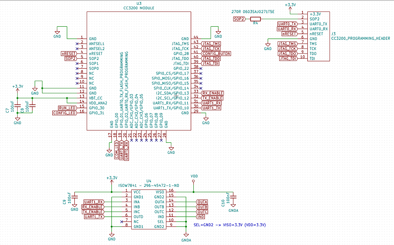
I designed a custom device using CC3200.
- servicepack_1.0.1.14-2.12.2.8.bin was loaded using Uniflash.
pinmux.c
#include "pinmux.h"
#include "hw_types.h"
#include "hw_memmap.h"
#include "hw_gpio.h"
#include "pin.h"
#include "rom.h"
#include "rom_map.h"
#include "gpio.h"
#include "prcm.h"

//*****************************************************************************
void
PinMuxConfig(void)
{
    //
        // Set unused pins to PIN_MODE_0 with the exception of JTAG pins 16,17,19,20
        //

        //
        // Enable Peripheral Clocks
        //
        MAP_PRCMPeripheralClkEnable(PRCM_GPIOA0, PRCM_RUN_MODE_CLK);
        MAP_PRCMPeripheralClkEnable(PRCM_GPIOA1, PRCM_RUN_MODE_CLK);
        MAP_PRCMPeripheralClkEnable(PRCM_GPIOA3, PRCM_RUN_MODE_CLK);
        MAP_PRCMPeripheralClkEnable(PRCM_UARTA0, PRCM_RUN_MODE_CLK);
        MAP_PRCMPeripheralClkEnable(PRCM_UARTA1, PRCM_RUN_MODE_CLK);

        //
        // Configure PIN_50 for GPIO Output
        //
        MAP_PinTypeGPIO(PIN_50, PIN_MODE_0, false);
        MAP_GPIODirModeSet(GPIOA0_BASE, 0x1, GPIO_DIR_MODE_OUT);

        //
        // Configure PIN_64 for GPIO Output
        //
        MAP_PinTypeGPIO(PIN_64, PIN_MODE_0, false);
        MAP_GPIODirModeSet(GPIOA1_BASE, 0x2, GPIO_DIR_MODE_OUT);

        //
        // Configure PIN_03 for GPIO Output
        //
        MAP_PinTypeGPIO(PIN_03, PIN_MODE_0, false);
        MAP_GPIODirModeSet(GPIOA1_BASE, 0x10, GPIO_DIR_MODE_OUT);

        //
        // Configure PIN_04 for GPIO Output
        //
        MAP_PinTypeGPIO(PIN_04, PIN_MODE_0, false);
        MAP_GPIODirModeSet(GPIOA1_BASE, 0x20, GPIO_DIR_MODE_OUT);

        //
        // Configure PIN_18 for GPIO Input
        //
        MAP_PinTypeGPIO(PIN_18, PIN_MODE_0, false);
        MAP_GPIODirModeSet(GPIOA3_BASE, 0x10, GPIO_DIR_MODE_IN);

        //
        // Configure PIN_53 for GPIO Output
        //
        MAP_PinTypeGPIO(PIN_53, PIN_MODE_0, false);
        MAP_GPIODirModeSet(GPIOA3_BASE, 0x40, GPIO_DIR_MODE_OUT);

        //
        // Configure PIN_45 for GPIO Output
        //
        MAP_PinTypeGPIO(PIN_45, PIN_MODE_0, false);
        MAP_GPIODirModeSet(GPIOA3_BASE, 0x80, GPIO_DIR_MODE_OUT);

        //
        // Configure PIN_55 for UART0 UART0_TX
        //
        MAP_PinTypeUART(PIN_55, PIN_MODE_3);

        //
        // Configure PIN_57 for UART0 UART0_RX
        //
        MAP_PinTypeUART(PIN_57, PIN_MODE_3);

        /*// IF THE TX AND RX PIN CONFIGURATION LINES ACTIVATED BELOW, THERE IS NO DATA AT TX PIN(GPIO_10).
        // Configure PIN_01 for UART1 UART1_TX
        //
        MAP_PinTypeUART(PIN_01, PIN_MODE_7);

        //
        // Configure PIN_02 for UART1 UART1_RX
        //
        MAP_PinTypeUART(PIN_02, PIN_MODE_7);*/

        // IF THE TX AND RX PIN CONFIGURATION LINES ACTIVATED BELOW, THERE IS DATA AT TX PIN(GPIO_03).
        //
        // Configure PIN_58 for UART1 UART1_TX
        //
        MAP_PinTypeUART(PIN_58, PIN_MODE_6);

        //
        // Configure PIN_59 for UART1 UART1_RX
        //
        MAP_PinTypeUART(PIN_59, PIN_MODE_6);


}
some part of uart_if.c
//*****************************************************************************
// Global variable indicating command is present
//*****************************************************************************
static unsigned long __Errorlog;

//*****************************************************************************
// Global variable indicating input length
//*****************************************************************************
unsigned int ilen=1;

#define UART1_BAUD_RATE  115200
#define SYSCLK1         80000000
#define CONSOLE1         UARTA1_BASE
#define CONSOLE1_PERIPH  PRCM_UARTA1


//*****************************************************************************
//
//! Initialization
//!
//! This function
//!        1. Configures the UART to be used.
//!
//! \return none
//
//*****************************************************************************
void
InitTerm()
{
#ifndef NOTERM

  MAP_UARTConfigSetExpClk(CONSOLE,MAP_PRCMPeripheralClockGet(CONSOLE_PERIPH),
                  UART_BAUD_RATE, (UART_CONFIG_WLEN_8 | UART_CONFIG_STOP_ONE |
                   UART_CONFIG_PAR_NONE));

  MAP_UARTConfigSetExpClk(UARTA1_BASE,MAP_PRCMPeripheralClockGet(PRCM_UARTA1),
                          UART_BAUD_RATE, (UART_CONFIG_WLEN_8 | UART_CONFIG_STOP_ONE |
                                  UART_CONFIG_PAR_NONE));


#endif

  __Errorlog = 0;


}
some part of main.c
void
Message1(const char *str)
{
    GPIO_IF_Set(COM_LED, mycom_led_port, mycom_led_pin, 1);
    UART_PRINT("\r\n .message1 called: \r\n");
#ifndef NOTERM
    if(str != NULL)
    {
        while(*str!='\0')
        {
            MAP_UARTCharPut(UARTA1_BASE,*str++);
            //MAP_UARTCharPut(UARTA1_BASE, *str++);
            UART_PRINT("X");
        }
    }

#endif
}


void LEDBlinkyRoutine()
{
    //
    // Toggle the lines initially to turn off the LEDs.
    // The values driven are as required by the LEDs on the LP.
    //

    while(1)
    {

        Message1("ppppppp");

        Message1("pppppppAAAA");


        GPIO_IF_Set(RUN_LED, my_led_port, my_led_pin, 1);
        MAP_UtilsDelay(1000000);
        GPIO_IF_Set(RUN_LED, my_led_port, my_led_pin, 0);
        MAP_UtilsDelay(1000000);


    }

}
When I active the lines below in pinmux.c, there is no data on UART1 tx pin:
// Configure PIN_01 for UART1 UART1_TX
        //
        MAP_PinTypeUART(PIN_01, PIN_MODE_7);

        //
        // Configure PIN_02 for UART1 UART1_RX
        //
        MAP_PinTypeUART(PIN_02, PIN_MODE_7);
BUT when I active the lines below, in pinmux.c, there is DATA on UART1 tx pin:
//
        // Configure PIN_58 for UART1 UART1_TX
        //
        MAP_PinTypeUART(PIN_58, PIN_MODE_6);

        //
        // Configure PIN_59 for UART1 UART1_RX
        //
        MAP_PinTypeUART(PIN_59, PIN_MODE_6);

Could you please help why I cannot configure the PIN_58 and PIN_59?
Best regards,
Onur