This thread has been locked.

If you have a related question, please click the "Ask a related question" button in the top right corner. The newly created question will be automatically linked to this question.

CC3235SF: Does the use of IO retention increase Hibernate current consumption, and if so, by how much

Part Number: CC3235SF
Other Parts Discussed in Thread: CC3235MODASF, SYSCONFIG, UNIFLASH, CCSTUDIO

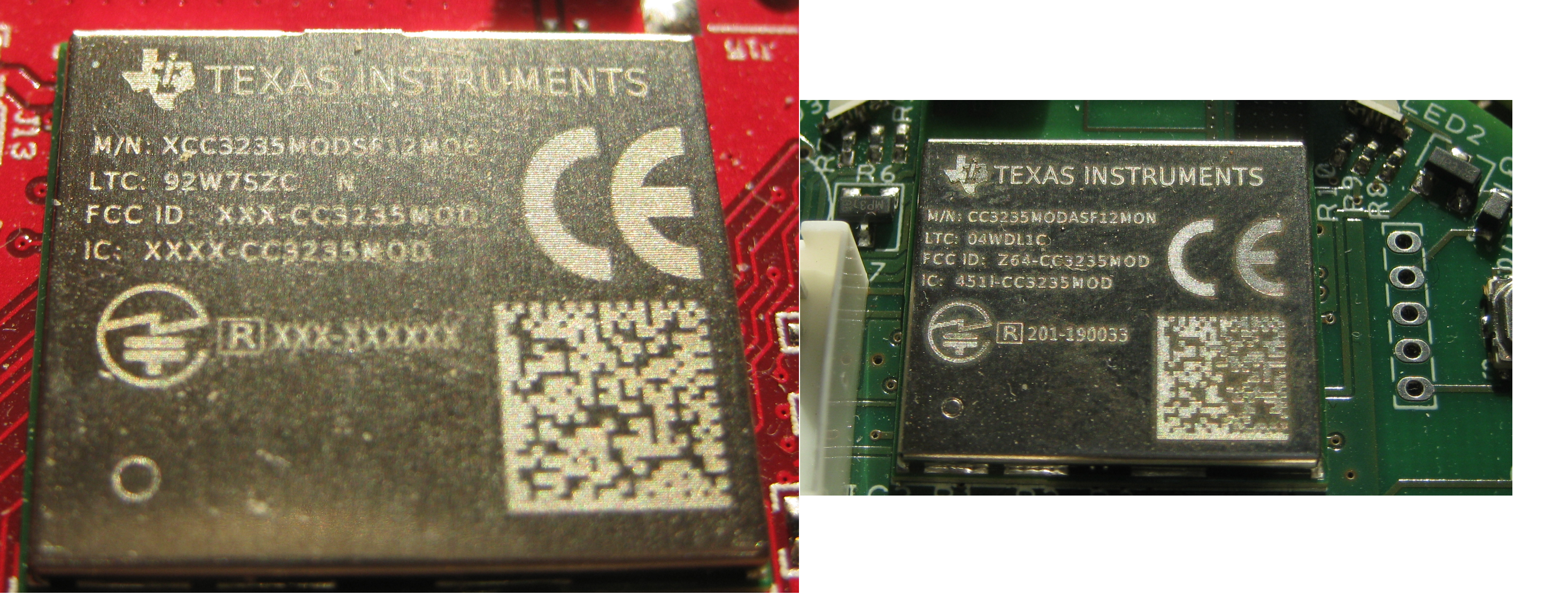
I have a custom CC3235MODASF board which is working fine, but the current consumption in Hibernate is about 50uA rather than the 5uA from the datasheet.

I am using the IO Retention functions to ensure that inputs do not float, and that outputs (which are inputs to FETs also cannot float.

Despite scouring the swra594a [Networking Subsystem Power Management], swru543a [Technical Reference Manual] and the device datasheet, I cannot find anything which states whether using the IO Retention functions add to the power consumption.

I should add that I have made quite sure that none of the parked IO's are actually driving any current - in all cases inputs are basically open circuit, and outputs are driving the gate of a MOSFET, so there should be no static current.

A secondary question - my application uses GP30, pin 42 on the module as an output, and this does not seem to be possible to park - certainly using the sysconfig tool in CCS version 10.0.0.00010

As it happens, this particular output - even when floating - does not compromise the rest of my board, so I can live with it, but I am just curious as to why this one is missing from the parkable set.

With thanks,

Chris

  • Hi Chris,

    IO retention is saved to the OCR registers, and the hibernate power consumption should include that. 50 uA is certainly too high. Are you using a custom board or a CC3235MOD LaunchPad? Have you gone through the hardware design checklist?

    There may be an issue with the SysConfig options for GPIO30, I will check on that.

    Best regards,

    Sarah

  • I believe I have followed the design checklist correctly.

    I may have found something:

    Using a 'scope, I can see that the SOP lines start low on power up - which is what I'd expect, as the datasheet implies they have 100k pull-downs inside the module.

    Howver, once the application is running I see they are going up to 3.3V (my Vbat voltage).

    Obviously I am pulling one of them up (with a resistor) when going into boot loader for programming, but have I accidentally included something which is pulling them high once the application starts up?

    With thanks,

    Chris

    .

  • Hi Chris,

    What SOP configuration are you using? To clarify, are you seeing that behavior on SOP0 (mod pin 34) and SOP1 (mod pin 24)? If you add an external pull-down instead of leaving those pins floating, does it change the power consumption?

    I also dug into the behavior of the IO retention function when entering hibernate. It does not seem to use the pin parking struct in SysConfig (this is for LPDS only). Instead, it parks the GPIOs in their current state before entering hibernate. Can you test manually setting the pins before entering hibernate and check for a change in power consumption?

    Best regards,

    Sarah

  • Hi Sarah,

    (sorry this post is rather long - there seem to be several things which may be inter-related, so I've NOT split them out to separate threads)

    Thanks for the tips on I/O Parking.  The application quite definitely sets GPIO 30 as an output on startup, and explicitly forces it (along with five others) to "high" before entering Hibernate.

    WRT the SOP issue, When the board is running, I am leaving all SOP inputs open circuit - i.e. 000.

    (during programming, I'm pulling SOP2 high with a 10k resistor

    However, if I 'scope the SOP lines on startupI get the following trace.  Yellow is system power, then going down the screen SOP0, SOP1, SOP2.

    As expected, SOP0 and SOP1 remain low the whole time.

    However, you can see that SOP2 pulses high for a short period just after power up, goes low for a while, then stays high indefinitely.

    My applicaiton puts the board into 'Hibernate' at about the 8 second mark, so SOP2 is staying high despite going into Hibernate (at 8 seconds, i.e. for the last two divisions)

    Zooming in to 200ms/div, and hiding SOP0 and SOP1:

     I can see The  SOP2 line is pulled high at about 14ms after power is applied.

    It stays high for 16ms then goes low

    It stays low for 1.35 seconds, then goes high.

    It stays high, even after the board goes into Hibernate at 8 seconds.

    With the probes rearranged so that top trace is power, second trace connected to a GPIO I am deliberatly controlling LED multiplexing) and bottom trace SOP2:

    I can see that SOP2 is going high probably about the same time I call GPIO init

    DC measurements with the chip powered down do imply that there is a 100k static resistance to Vss, so this behaviour is contributing 33uA to my standby current, which would pretty much explain the excess.

    The dataheet contains the following statements

    The statement that the line is 'Driven Low' during Hibernate appears to be patently false!

    I also note from the datasheet that SOP2 has an alter ego of GPIO25.  Could it be that the auto-generated GPIO initialisation is trying to control this pin, even though there is no reference to it in the CCI Sysconfig GUI?

    Is it a coincidence that - as discussed - GPIO30 is apparently *not* getting configured entirely correctly?  Perhaps some code which is meant to be hitting GPIO30 is actually clobbering GPIO25?

    I would be happy to send you my project as a PM, but prefer not to post it publicly.

    Thanks in advance for your help

    Chris

  • Hi Chris,

    Can you re-add your images or let me know what page you are referring to? There may be some differences in the hardware default explained in the datasheet versus what the power policy is implementing in software.

    Can you attach your ti_drivers_config.c file to this post? This will be in the Debug/syscfg folder of your project. It is the generated configuration source that is the SysConfig tool output, so it should not contain sensitive information.

    Best regards,

    Sarah

  • Hi Sarah,

    Please see below the three 'scope shots which I hope are now visible.

    HI Sarah,

    I have tried to re-insert the 'scope images using the picture of a paper clip (I can't find a way to simply "attach" a file, it only seems possible to insert it)

    The documentation points I was referring to are in SWRS243, version Feb 2020

    The first is Page 25, Table 4.2, relating to Pkg Pin 23

    The second is footnote 5 on page 37, Table 4-3

    I have attempted to attach/insert the ti_drivers_config.c file below - all I can see is a huge graphic of a folder.  Perhaps it will work for you?  as 'belt and braces', I have copied the file to Dropbox with a public link being:

    www.dropbox.com/.../ti_drivers_config.c

    6712.ti_drivers_config.c
    /*
     *  ======== ti_drivers_config.c ========
     *  Configured TI-Drivers module definitions
     *
     *  DO NOT EDIT - This file is generated for the CC3235SF
     *  by the SysConfig tool.
     */
    
    #include <stddef.h>
    #include <stdint.h>
    
    #ifndef DeviceFamily_CC3220
    #define DeviceFamily_CC3220
    #endif
    
    #include <ti/devices/DeviceFamily.h>
    
    #include "ti_drivers_config.h"
    
    
    /*
     *  ============================= Display =============================
     */
    
    #include <ti/display/Display.h>
    #include <ti/display/DisplayUart.h>
    
    #define CONFIG_Display_COUNT 1
    
    #define Display_UARTBUFFERSIZE 1024
    static char displayUARTBuffer[Display_UARTBUFFERSIZE];
    
    DisplayUart_Object displayUartObject;
    
    const DisplayUart_HWAttrs displayUartHWAttrs = {
        .uartIdx      = CONFIG_UART_0,
        .baudRate     = 115200,
        .mutexTimeout = (unsigned int)(-1),
        .strBuf       = displayUARTBuffer,
        .strBufLen    = Display_UARTBUFFERSIZE
    };
    
    const Display_Config Display_config[CONFIG_Display_COUNT] = {
        /* CONFIG_Display_0 */
        {
            .fxnTablePtr = &DisplayUartMin_fxnTable,
            .object      = &displayUartObject,
            .hwAttrs     = &displayUartHWAttrs
        },
    };
    
    const uint_least8_t Display_count = CONFIG_Display_COUNT;
    
    
    /*
     *  =============================== ADC ===============================
     */
    
    #include <ti/drivers/ADC.h>
    #include <ti/drivers/adc/ADCCC32XX.h>
    
    #include <ti/devices/cc32xx/driverlib/adc.h>
    
    #define CONFIG_ADC_COUNT 1
    
    /*
     *  ======== adcCCC32XXObjects ========
     */
    ADCCC32XX_Object adcCC32XXObjects[CONFIG_ADC_COUNT];
    
    /*
     *  ======== adcCC3220SHWAttrs ========
     */
    const ADCCC32XX_HWAttrsV1 adcCC32XXHWAttrs[CONFIG_ADC_COUNT] = {
        /* BATT_SENS_CH1 */
        {
            .adcPin = ADCCC32XX_PIN_58_CH_1,
        },
    };
    
    /*
     *  ======== ADC_config ========
     */
    const ADC_Config ADC_config[CONFIG_ADC_COUNT] = {
        /* BATT_SENS_CH1 */
        {
            .fxnTablePtr = &ADCCC32XX_fxnTable,
            .object = &adcCC32XXObjects[BATT_SENS_CH1],
            .hwAttrs = &adcCC32XXHWAttrs[BATT_SENS_CH1]
        },
    };
    
    const uint_least8_t BATT_SENS_CH1_CONST = BATT_SENS_CH1;
    const uint_least8_t ADC_count = CONFIG_ADC_COUNT;
    
    
    /*
     *  =============================== Crypto ===============================
     */
    
    #include <ti/drivers/crypto/CryptoCC32XX.h>
    
    /*
     *  ======== CryptoCC32XXObjects ========
     */
    #define CONFIG_Crypto_COUNT 1
    CryptoCC32XX_Object cryptoCC32XXObjects[CONFIG_Crypto_COUNT];
    
    /*
     *  ======== Crypto_config ========
     */
    const CryptoCC32XX_Config CryptoCC32XX_config[CONFIG_Crypto_COUNT] = {
        /* CONFIG_Crypto_0 */
        {
            .object = &cryptoCC32XXObjects[CONFIG_Crypto_0],
        },
    };
    
    const uint_least8_t CONFIG_Crypto_0_CONST = CONFIG_Crypto_0;
    const uint_least8_t CryptoCC32XX_count = CONFIG_Crypto_COUNT;
    
    
    /*
     *  =============================== DMA ===============================
     */
    
    #include <ti/drivers/dma/UDMACC32XX.h>
    #include <ti/devices/cc32xx/inc/hw_ints.h>
    #include <ti/devices/cc32xx/inc/hw_types.h>
    #include <ti/devices/cc32xx/driverlib/rom_map.h>
    #include <ti/devices/cc32xx/driverlib/udma.h>
    
    /* Ensure DMA control table is aligned as required by the uDMA Hardware */
    static tDMAControlTable dmaControlTable[64] __attribute__ ((aligned (1024)));
    
    /* This is the handler for the uDMA error interrupt. */
    static void dmaErrorFxn(uintptr_t arg)
    {
        int status = MAP_uDMAErrorStatusGet();
        MAP_uDMAErrorStatusClear();
    
        /* Suppress unused variable warning */
        (void)status;
    
        while (1);
    }
    
    UDMACC32XX_Object udmaCC3220SObject;
    
    const UDMACC32XX_HWAttrs udmaCC3220SHWAttrs = {
        .controlBaseAddr = (void *)dmaControlTable,
        .dmaErrorFxn     = (UDMACC32XX_ErrorFxn)dmaErrorFxn,
        .intNum          = INT_UDMAERR,
        .intPriority     = (~0)
    };
    
    const UDMACC32XX_Config UDMACC32XX_config = {
        .object  = &udmaCC3220SObject,
        .hwAttrs = &udmaCC3220SHWAttrs
    };
    
    
    /*
     *  =============================== GPIO ===============================
     */
    
    #include <ti/drivers/GPIO.h>
    #include <ti/drivers/gpio/GPIOCC32XX.h>
    
    #define CONFIG_GPIO_COUNT 16
    
    /*
     *  ======== gpioPinConfigs ========
     *  Array of Pin configurations
     */
    GPIO_PinConfig gpioPinConfigs[] = {
        /* LED1A */
        GPIOCC32XX_GPIO_05 | GPIO_CFG_OUT_STD | GPIO_CFG_OUT_STR_MED | GPIO_CFG_OUT_HIGH | GPIOCC32XX_USE_STATIC,
        /* LED2A */
        GPIOCC32XX_GPIO_28 | GPIO_CFG_OUT_STD | GPIO_CFG_OUT_STR_MED | GPIO_CFG_OUT_HIGH | GPIOCC32XX_USE_STATIC,
        /* LED3A */
        GPIOCC32XX_GPIO_30 | GPIO_CFG_OUT_STD | GPIO_CFG_OUT_STR_MED | GPIO_CFG_OUT_HIGH | GPIOCC32XX_USE_STATIC,
        /* LED4A */
        GPIOCC32XX_GPIO_08 | GPIO_CFG_OUT_STD | GPIO_CFG_OUT_STR_MED | GPIO_CFG_OUT_HIGH | GPIOCC32XX_USE_STATIC,
        /* LED5A */
        GPIOCC32XX_GPIO_09 | GPIO_CFG_OUT_STD | GPIO_CFG_OUT_STR_MED | GPIO_CFG_OUT_HIGH | GPIOCC32XX_USE_STATIC,
        /* LED6A */
        GPIOCC32XX_GPIO_10 | GPIO_CFG_OUT_STD | GPIO_CFG_OUT_STR_MED | GPIO_CFG_OUT_HIGH | GPIOCC32XX_USE_STATIC,
        /* LEDRed */
        GPIOCC32XX_GPIO_16 | GPIO_CFG_OUT_STD | GPIO_CFG_OUT_STR_MED | GPIO_CFG_OUT_LOW | GPIOCC32XX_USE_STATIC,
        /* LEDGreen */
        GPIOCC32XX_GPIO_15 | GPIO_CFG_OUT_STD | GPIO_CFG_OUT_STR_MED | GPIO_CFG_OUT_LOW | GPIOCC32XX_USE_STATIC,
        /* LEDBlue */
        GPIOCC32XX_GPIO_14 | GPIO_CFG_OUT_STD | GPIO_CFG_OUT_STR_MED | GPIO_CFG_OUT_LOW | GPIOCC32XX_USE_STATIC,
        /* BUT1 */
        GPIOCC32XX_GPIO_02 | GPIO_CFG_IN_PU | GPIO_CFG_IN_INT_NONE | GPIOCC32XX_USE_STATIC,
        /* BUT2 */
        GPIOCC32XX_GPIO_04 | GPIO_CFG_IN_PU | GPIO_CFG_IN_INT_NONE | GPIOCC32XX_USE_STATIC,
        /* BUT3 */
        GPIOCC32XX_GPIO_11 | GPIO_CFG_IN_PU | GPIO_CFG_IN_INT_NONE | GPIOCC32XX_USE_STATIC,
        /* BUT4 */
        GPIOCC32XX_GPIO_17 | GPIO_CFG_IN_PU | GPIO_CFG_IN_INT_NONE | GPIOCC32XX_USE_STATIC,
        /* BUT5 */
        GPIOCC32XX_GPIO_13 | GPIO_CFG_IN_PU | GPIO_CFG_IN_INT_NONE | GPIOCC32XX_USE_STATIC,
        /* HAPTIC */
        GPIOCC32XX_GPIO_00 | GPIO_CFG_OUT_STD | GPIO_CFG_OUT_STR_MED | GPIO_CFG_OUT_LOW | GPIOCC32XX_USE_STATIC,
        /* SETUP */
        GPIOCC32XX_GPIO_22 | GPIO_CFG_IN_PU | GPIO_CFG_IN_INT_NONE | GPIOCC32XX_USE_STATIC,
    };
    
    /*
     *  ======== gpioCallbackFunctions ========
     *  Array of callback function pointers
     *
     *  NOTE: Unused callback entries can be omitted from the callbacks array to
     *  reduce memory usage by enabling callback table optimization
     *  (GPIO.optimizeCallbackTableSize = true)
     */
    GPIO_CallbackFxn gpioCallbackFunctions[] = {
        /* LED1A */
        NULL,
        /* LED2A */
        NULL,
        /* LED3A */
        NULL,
        /* LED4A */
        NULL,
        /* LED5A */
        NULL,
        /* LED6A */
        NULL,
        /* LEDRed */
        NULL,
        /* LEDGreen */
        NULL,
        /* LEDBlue */
        NULL,
        /* BUT1 */
        NULL,
        /* BUT2 */
        NULL,
        /* BUT3 */
        NULL,
        /* BUT4 */
        NULL,
        /* BUT5 */
        NULL,
        /* HAPTIC */
        NULL,
        /* SETUP */
        NULL,
    };
    
    const uint_least8_t LED1A_CONST = LED1A;
    const uint_least8_t LED2A_CONST = LED2A;
    const uint_least8_t LED3A_CONST = LED3A;
    const uint_least8_t LED4A_CONST = LED4A;
    const uint_least8_t LED5A_CONST = LED5A;
    const uint_least8_t LED6A_CONST = LED6A;
    const uint_least8_t LEDRed_CONST = LEDRed;
    const uint_least8_t LEDGreen_CONST = LEDGreen;
    const uint_least8_t LEDBlue_CONST = LEDBlue;
    const uint_least8_t BUT1_CONST = BUT1;
    const uint_least8_t BUT2_CONST = BUT2;
    const uint_least8_t BUT3_CONST = BUT3;
    const uint_least8_t BUT4_CONST = BUT4;
    const uint_least8_t BUT5_CONST = BUT5;
    const uint_least8_t HAPTIC_CONST = HAPTIC;
    const uint_least8_t SETUP_CONST = SETUP;
    
    /*
     *  ======== GPIOCC32XX_config ========
     */
    const GPIOCC32XX_Config GPIOCC32XX_config = {
        .pinConfigs = (GPIO_PinConfig *)gpioPinConfigs,
        .callbacks = (GPIO_CallbackFxn *)gpioCallbackFunctions,
        .numberOfPinConfigs = 16,
        .numberOfCallbacks = 16,
        .intPriority = (~0)
    };
    
    
    /*
     *  =============================== Power ===============================
     */
    #include <ti/drivers/Power.h>
    #include <ti/drivers/power/PowerCC32XX.h>
    #include <ti/devices/cc32xx/driverlib/prcm.h>
    
    extern void PowerCC32XX_initPolicy(void);
    extern void PowerCC32XX_sleepPolicy(void);
    PowerCC32XX_ParkInfo parkInfo[];
    /*
     *  This structure defines the configuration for the Power Manager.
     */
    const PowerCC32XX_ConfigV1 PowerCC32XX_config = {
        .policyInitFxn             = PowerCC32XX_initPolicy,
        .policyFxn                 = PowerCC32XX_sleepPolicy,
        .enterLPDSHookFxn          = NULL,
        .resumeLPDSHookFxn         = NULL,
        .enablePolicy              = false,
        .enableGPIOWakeupLPDS      = false,
        .enableGPIOWakeupShutdown  = false,
        .enableNetworkWakeupLPDS   = true,
        .wakeupGPIOSourceLPDS      = PRCM_LPDS_GPIO13,
        .wakeupGPIOTypeLPDS        = PRCM_LPDS_FALL_EDGE,
        .wakeupGPIOFxnLPDS         = NULL,
        .wakeupGPIOFxnLPDSArg      = 0,
        .wakeupGPIOSourceShutdown  = PRCM_HIB_GPIO13,
        .wakeupGPIOTypeShutdown    = PRCM_HIB_RISE_EDGE,
        .ramRetentionMaskLPDS      = PRCM_SRAM_COL_1|PRCM_SRAM_COL_2|PRCM_SRAM_COL_3|PRCM_SRAM_COL_4,
        .keepDebugActiveDuringLPDS = false,
        .ioRetentionShutdown       = PRCM_IO_RET_GRP_0|PRCM_IO_RET_GRP_1,
        .pinParkDefs               = parkInfo,
        .numPins                   = 31
    };
    
    
    /*
     *  =============================== SPI ===============================
     */
    
    #include <ti/drivers/SPI.h>
    #include <ti/drivers/spi/SPICC32XXDMA.h>
    
    #include <ti/devices/cc32xx/inc/hw_ints.h>
    #include <ti/devices/cc32xx/inc/hw_memmap.h>
    #include <ti/devices/cc32xx/inc/hw_types.h>
    #include <ti/devices/cc32xx/driverlib/prcm.h>
    #include <ti/devices/cc32xx/driverlib/spi.h>
    #include <ti/devices/cc32xx/driverlib/udma.h>
    
    #define CONFIG_SPI_COUNT 1
    
    /*
     *  ======== spiCC32XXDMAObjects ========
     */
    SPICC32XXDMA_Object spiCC32XXDMAObjects[CONFIG_SPI_COUNT];
    
    uint32_t spiCC32XXSDMAscratchBuf[CONFIG_SPI_COUNT];
    
    /*
     *  ======== spiCC32XXDMAHWAttrs ========
     */
    const SPICC32XXDMA_HWAttrsV1 spiCC32XXDMAHWAttrs[CONFIG_SPI_COUNT] = {
        /* CONFIG_NWP_SPI */
        /* Network Processor SPI Bus */
        {
            .baseAddr = LSPI_BASE,
            .intNum = INT_LSPI,
            .intPriority = (~0),
            .spiPRCM = PRCM_LSPI,
            .csControl = SPI_SW_CTRL_CS,
            .csPolarity = SPI_CS_ACTIVEHIGH,
            .pinMode = SPI_4PIN_MODE,
            .turboMode = SPI_TURBO_OFF,
            .scratchBufPtr = &spiCC32XXSDMAscratchBuf[CONFIG_NWP_SPI],
            .defaultTxBufValue = 0,
            .rxChannelIndex = UDMA_CH12_LSPI_RX,
            .txChannelIndex = UDMA_CH13_LSPI_TX,
            .minDmaTransferSize = 100,
            .mosiPin = SPICC32XXDMA_PIN_NO_CONFIG,
            .misoPin = SPICC32XXDMA_PIN_NO_CONFIG,
            .clkPin  = SPICC32XXDMA_PIN_NO_CONFIG,
            .csPin  = SPICC32XXDMA_PIN_NO_CONFIG
        },
    };
    
    /*
     *  ======== SPI_config ========
     */
    const SPI_Config SPI_config[CONFIG_SPI_COUNT] = {
        /* CONFIG_NWP_SPI */
        {
            .fxnTablePtr = &SPICC32XXDMA_fxnTable,
            .object = &spiCC32XXDMAObjects[CONFIG_NWP_SPI],
            .hwAttrs = &spiCC32XXDMAHWAttrs[CONFIG_NWP_SPI]
        },
    };
    
    
    const uint_least8_t CONFIG_NWP_SPI_CONST = CONFIG_NWP_SPI;
    const uint_least8_t SPI_count = CONFIG_SPI_COUNT;
    
    
    /*
     *  =============================== Timer ===============================
     */
    
    #include <ti/drivers/Timer.h>
    #include <ti/devices/cc32xx/inc/hw_memmap.h>
    #include <ti/devices/cc32xx/inc/hw_ints.h>
    #include <ti/drivers/timer/TimerCC32XX.h>
    
    #define CONFIG_TIMER_COUNT 4
    
    /*
     *  ======== timerCC32XXObjects ========
     */
    TimerCC32XX_Object timerCC32XXObjects[CONFIG_TIMER_COUNT];
    
    /*
     *  ======== timerCC32XXHWAttrs ========
     */
    const TimerCC32XX_HWAttrs timerCC32XXHWAttrs[CONFIG_TIMER_COUNT] = {
        /* CONFIG_TIMER_0 */
        {
            .baseAddress = TIMERA0_BASE,
            .subTimer    = TimerCC32XX_timer32,
            .intNum      = INT_TIMERA0A,
            .intPriority = (~0)
        },
        /* CONFIG_TIMER_1 */
        {
            .baseAddress = TIMERA1_BASE,
            .subTimer    = TimerCC32XX_timer16A,
            .intNum      = INT_TIMERA1A,
            .intPriority = (~0)
        },
        /* CONFIG_TIMER_2 */
        {
            .baseAddress = TIMERA1_BASE,
            .subTimer    = TimerCC32XX_timer16B,
            .intNum      = INT_TIMERA1B,
            .intPriority = (~0)
        },
        /* CONFIG_TIMER_3 */
        {
            .baseAddress = TIMERA2_BASE,
            .subTimer    = TimerCC32XX_timer16A,
            .intNum      = INT_TIMERA2A,
            .intPriority = (~0)
        },
    };
    
    /*
     *  ======== Timer_config ========
     */
    const Timer_Config Timer_config[CONFIG_TIMER_COUNT] = {
        /* CONFIG_TIMER_0 */
        {
            .fxnTablePtr = &TimerCC32XX_fxnTable,
            .object      = &timerCC32XXObjects[CONFIG_TIMER_0],
            .hwAttrs     = &timerCC32XXHWAttrs[CONFIG_TIMER_0]
        },
        /* CONFIG_TIMER_1 */
        {
            .fxnTablePtr = &TimerCC32XX_fxnTable,
            .object      = &timerCC32XXObjects[CONFIG_TIMER_1],
            .hwAttrs     = &timerCC32XXHWAttrs[CONFIG_TIMER_1]
        },
        /* CONFIG_TIMER_2 */
        {
            .fxnTablePtr = &TimerCC32XX_fxnTable,
            .object      = &timerCC32XXObjects[CONFIG_TIMER_2],
            .hwAttrs     = &timerCC32XXHWAttrs[CONFIG_TIMER_2]
        },
        /* CONFIG_TIMER_3 */
        {
            .fxnTablePtr = &TimerCC32XX_fxnTable,
            .object      = &timerCC32XXObjects[CONFIG_TIMER_3],
            .hwAttrs     = &timerCC32XXHWAttrs[CONFIG_TIMER_3]
        },
    };
    
    const uint_least8_t CONFIG_TIMER_0_CONST = CONFIG_TIMER_0;
    const uint_least8_t CONFIG_TIMER_1_CONST = CONFIG_TIMER_1;
    const uint_least8_t CONFIG_TIMER_2_CONST = CONFIG_TIMER_2;
    const uint_least8_t CONFIG_TIMER_3_CONST = CONFIG_TIMER_3;
    const uint_least8_t Timer_count = CONFIG_TIMER_COUNT;
    
    
    /*
     *  =============================== UART ===============================
     */
    
    #include <ti/drivers/UART.h>
    #include <ti/devices/cc32xx/inc/hw_ints.h>
    #include <ti/devices/cc32xx/inc/hw_memmap.h>
    #include <ti/drivers/uart/UARTCC32XXDMA.h>
    
    #define CONFIG_UART_COUNT 1
    
    #define UART0_BASE UARTA0_BASE
    #define UART1_BASE UARTA1_BASE
    #define INT_UART0  INT_UARTA0
    #define INT_UART1  INT_UARTA1
    
    
    UARTCC32XXDMA_Object uartCC32XXObjects0;
    
    static const UARTCC32XXDMA_HWAttrsV1 uartCC32XXHWAttrs0 = {
        .baseAddr           = UART0_BASE,
        .intNum             = INT_UART0,
        .intPriority        = (~0),
        .flowControl        = UARTCC32XXDMA_FLOWCTRL_NONE,
        .rxChannelIndex     = UDMA_CH8_UARTA0_RX,
        .txChannelIndex     = UDMA_CH9_UARTA0_TX,
        .rxPin              = UARTCC32XXDMA_PIN_57_UART0_RX,
        .txPin              = UARTCC32XXDMA_PIN_55_UART0_TX,
        .ctsPin             = UARTCC32XXDMA_PIN_UNASSIGNED,
        .rtsPin             = UARTCC32XXDMA_PIN_UNASSIGNED,
        .errorFxn           = NULL
      };
    
    const UART_Config UART_config[CONFIG_UART_COUNT] = {
        {   /* CONFIG_UART_0 */
            .fxnTablePtr = &UARTCC32XXDMA_fxnTable,
            .object      = &uartCC32XXObjects0,
            .hwAttrs     = &uartCC32XXHWAttrs0
        },
    };
    
    const uint_least8_t CONFIG_UART_0_CONST = CONFIG_UART_0;
    const uint_least8_t UART_count = CONFIG_UART_COUNT;


    /*
     *  =============================== Watchdog ===============================
     */
    
    #include <ti/drivers/Watchdog.h>
    #include <ti/drivers/watchdog/WatchdogCC32XX.h>
    #include <ti/devices/cc32xx/inc/hw_memmap.h>
    #include <ti/devices/cc32xx/inc/hw_ints.h>
    #include <ti/devices/cc32xx/inc/hw_types.h>
    #include <ti/devices/cc32xx/driverlib/wdt.h>
    
    #define CONFIG_WATCHDOG_COUNT 1
    
    WatchdogCC32XX_Object watchdogCC32XXObjects[CONFIG_WATCHDOG_COUNT];
    
    const WatchdogCC32XX_HWAttrs
        watchdogCC32XXHWAttrs[CONFIG_WATCHDOG_COUNT] = {
        /* CONFIG_WATCHDOG_0: period = 1000 */
        {
            .baseAddr    = WDT_BASE,
            .intNum      = INT_WDT,
            .intPriority = 0x20,
            .reloadValue = 80000000
        },
    };
    
    const Watchdog_Config Watchdog_config[CONFIG_WATCHDOG_COUNT] = {
        /* CONFIG_WATCHDOG_0 */
        {
            .fxnTablePtr = &WatchdogCC32XX_fxnTable,
            .object      = &watchdogCC32XXObjects[CONFIG_WATCHDOG_0],
            .hwAttrs     = &watchdogCC32XXHWAttrs[CONFIG_WATCHDOG_0]
        }
    };
    
    const uint_least8_t CONFIG_WATCHDOG_0_CONST = CONFIG_WATCHDOG_0;
    const uint_least8_t Watchdog_count = CONFIG_WATCHDOG_COUNT;
    
    
    #include <ti/drivers/power/PowerCC32XX.h>
    
    /*
     * This table defines the parking state to be set for each parkable pin
     * during LPDS. (Device resources must be parked during LPDS to achieve maximum
     * power savings.)  If the pin should be left unparked, specify the state
     * PowerCC32XX_DONT_PARK.  For example, for a UART TX pin, the device
     * will automatically park the pin in a high state during transition to LPDS,
     * so the Power Manager does not need to explictly park the pin.  So the
     * corresponding entries in this table should indicate PowerCC32XX_DONT_PARK.
     */
    PowerCC32XX_ParkInfo parkInfo[] = {
    /*        PIN                    PARK STATE              Pin Alias
       -----------------  ------------------------------     ---------------*/
    
      {PowerCC32XX_PIN01, PowerCC32XX_WEAK_PULL_DOWN_STD},
      {PowerCC32XX_PIN02, PowerCC32XX_WEAK_PULL_DOWN_STD},
      {PowerCC32XX_PIN03, PowerCC32XX_WEAK_PULL_DOWN_STD},   /* GP10 */
      {PowerCC32XX_PIN04, PowerCC32XX_WEAK_PULL_DOWN_STD},   /* GP11 */
      {PowerCC32XX_PIN05, PowerCC32XX_WEAK_PULL_DOWN_STD},   /* GP14 */
      {PowerCC32XX_PIN06, PowerCC32XX_WEAK_PULL_DOWN_STD},   /* GP15 */
      {PowerCC32XX_PIN07, PowerCC32XX_WEAK_PULL_DOWN_STD},   /* GP16 */
      {PowerCC32XX_PIN08, PowerCC32XX_WEAK_PULL_DOWN_STD},   /* GP17 */
      {PowerCC32XX_PIN13, PowerCC32XX_WEAK_PULL_DOWN_STD},
      {PowerCC32XX_PIN15, PowerCC32XX_WEAK_PULL_DOWN_STD},
      {PowerCC32XX_PIN16, PowerCC32XX_WEAK_PULL_DOWN_STD},
      {PowerCC32XX_PIN17, PowerCC32XX_WEAK_PULL_DOWN_STD},
      {PowerCC32XX_PIN18, PowerCC32XX_WEAK_PULL_DOWN_STD},   /* TDO */
      {PowerCC32XX_PIN19, PowerCC32XX_WEAK_PULL_UP_STD},   /* GP28 */
      {PowerCC32XX_PIN20, PowerCC32XX_WEAK_PULL_DOWN_STD},
      {PowerCC32XX_PIN21, PowerCC32XX_WEAK_PULL_DOWN_STD},   /* TCK */
      {PowerCC32XX_PIN29, PowerCC32XX_WEAK_PULL_DOWN_STD},
      {PowerCC32XX_PIN30, PowerCC32XX_WEAK_PULL_DOWN_STD},
      {PowerCC32XX_PIN45, PowerCC32XX_WEAK_PULL_DOWN_STD},
      {PowerCC32XX_PIN50, PowerCC32XX_WEAK_PULL_UP_STD},   /* GP05 */
      {PowerCC32XX_PIN52, PowerCC32XX_WEAK_PULL_DOWN_STD},   /* GP07 */
      {PowerCC32XX_PIN53, PowerCC32XX_WEAK_PULL_DOWN_STD},   /* GP08 */
      {PowerCC32XX_PIN55, PowerCC32XX_WEAK_PULL_UP_STD},
      {PowerCC32XX_PIN57, PowerCC32XX_WEAK_PULL_UP_STD},
      {PowerCC32XX_PIN58, PowerCC32XX_WEAK_PULL_DOWN_STD},
      {PowerCC32XX_PIN59, PowerCC32XX_WEAK_PULL_DOWN_STD},
      {PowerCC32XX_PIN60, PowerCC32XX_WEAK_PULL_DOWN_STD},
      {PowerCC32XX_PIN61, PowerCC32XX_WEAK_PULL_DOWN_STD},
      {PowerCC32XX_PIN62, PowerCC32XX_WEAK_PULL_DOWN_STD},
      {PowerCC32XX_PIN63, PowerCC32XX_WEAK_PULL_DOWN_STD},
      {PowerCC32XX_PIN64, PowerCC32XX_WEAK_PULL_DOWN_STD},
    };
    
    
    #include <ti/drivers/Board.h>
    
    /*
     *  ======== Board_initHook ========
     *  Perform any board-specific initialization needed at startup.  This
     *  function is declared weak to allow applications to override it if needed.
     */
    void __attribute__((weak)) Board_initHook(void)
    {
    }
    
    /*
     *  ======== Board_init ========
     *  Perform any initialization needed before using any board APIs
     */
    void Board_init(void)
    {
        /* ==== /ti/drivers/Power initialization ==== */
        PRCMCC3200MCUInit();
        Power_init();
    
        Board_initHook();
    }
    
    /*
     *  ======== Board_debugHeader ========
     *  This structure prevents the CC32XXSF bootloader from overwriting the
     *  internal FLASH; this allows us to flash a program that will not be
     *  overwritten by the bootloader with the encrypted program saved in
     *  "secure/serial flash".
     *
     *  This structure must be placed at the beginning of internal FLASH (so
     *  the bootloader is able to recognize that it should not overwrite
     *  internal FLASH).
     */
    #if defined (__SF_DEBUG__) || defined(__SF_NODEBUG__)
    #if defined(__TI_COMPILER_VERSION__)
    #pragma DATA_SECTION(Board_debugHeader, ".dbghdr")
    #pragma RETAIN(Board_debugHeader)
    #elif defined(__IAR_SYSTEMS_ICC__)
    #pragma location=".dbghdr"
    #elif defined(__GNUC__)
    __attribute__ ((section (".dbghdr")))
    #endif
    #if defined(__SF_DEBUG__)
    const uint32_t Board_debugHeader[] = {
        0x5AA5A55A,
        0x000FF800,
        0xEFA3247D
    };
    #elif defined (__SF_NODEBUG__)
    const uint32_t Board_debugHeader[] = {
        0xFFFFFFFF,
        0xFFFFFFFF,
        0xFFFFFFFF
    };
    #endif
    #endif
    

    Thanks in advance for your help,

    Chris

  • Hi Chris,

    Thank you for providing all of that information. Your file came through correctly, although I do not see anything in software that would be configuring that pin. I will pull in one of the hardware engineers to assist further.

    Best regards,

    Sarah

  • Hi Sarah - any idea when we might hear back from the hardware side?

    With thanks,

    Chris

  • Hi Chris,

    We reviewed your scope captures, and we believe there is still a software explanation.

    Are you able to run your application on a LaunchPad and observe the same SOP2 output? If so, I can try debugging further on my setup.

    Best regards,

    Sarah

  • I can confirm that the same SOP2 behaviour occurs on my LaunchPad board

    Top trace is the reset line, bottom trace is SOP2

    The sequence of events on start-up are as follows:

    Source file main_tirtos.c creates and starts a thread which runs a procedure called MainThread()

    MainThread() calls two subroutines:

        PRCMIORetentionDisable(IO_RETAIN);  //Unlock pins
        GPIO_init();

    and GPIO_init()  is part of the SDK.

    As a test, I added a while (1) ;

    statement before the PRCMIORetentionDisable() statement.

    I found that the SOP2 line *still* goes high even though the unlock is never called, and GPIO_init is never called.

    This makes me wonder if there is something happening at a lower level ("BIOS?") rather than a bug in the GPIO_init() area.

    I have spent some time trying to fathom out the detail of how GPIO_init() works, but I ended up with an aching brain, befuddled by pad numbers, register numbers, pin numbers on the IC, pin numbers on the module, from the various datasheets.  But to my shame, I have so far failed to build a coherent software-to-hardware picture in my head!

    Now I am pulling SOP2 high to force the module into bootloader mode when I program the flash.

    Is it possible that this state of SOP2 is being "remembered" and restored somehow?

    I should add that I had a right struggle with the bootloader and Uniflash, and found that using SOP with 0b100 was the only way I could reliably connect and program the module using Uniflash.  I know the chip is supposed to enter boot loader briefly on power up with other SOP combinations, but I could not get that to work.

  • OK, so I've found a workaround.  Having worked out that the SOP2 line is somehow being configured as an output before I get control, I looked in the Sysconfig stuff, and found that it is possible to create a GPIO in my project which uses the SOP2 pin.

    By building that pin explicitly as an input, I find that the SOP2 line now pulses high twice on startup.

    First, aboout 12ms after the reset line goes high, we see a pulse around 12.5ms long.

    Second, about 1.1 second after the reset line goes high, a second pulse about 42ms long, which I believe to be the "mystery code" setting the GPIO as a high output, followed by my call go GPIO_Init() making it an input - at which point the internal 100k pulldown ensures the line is low

    So I'm now officially a Happy Bunny, with my Hibernate current now measuring well under 5uA

    I would still be interested to know if my 'fix' is simply covering up an underlying issue which I should address, but at least it is not now an operational issue.

    Thanks as ever,

    Chris

  • Hi Chris,

    I'm glad you found a workaround! I will continue looking into this issue to see if we can identify a cause.

    Can you clarify which CC32xx SDK version you are using?

    Best regards,

    Sarah

  • Hi Sarah,

    I'm using SDK version 4_20_00_07

    CCS 10.0.0.00010

      Sys Config    1.4.0.1234    com.ti.ccstudio.sysconfig.feature.group    Texas Instruments

      TI-RTOS for CC32XX (IDE Client)    2.16.1.14    com.ti.rtsc.TIRTOSCC32XX.product.ui.feature.group    Texas Instruments

    My LaunchPad uses the "MOD" version of the module, and my production boards use the "MODA" version.

    Here are photos of the information on the top of the two devices:

     _

    Let me know if you need any further version information

  • Just wondered if you'd been able to make any further progress with this?  Is there any more info I can provide you with?

    Best,

    Chris

  • Hi Chris,

    Unfortunately I have not made progress on this issue yet, due to the U.S. holiday last week. I do not need any further info right now, and I will try to provide an update this week.

    Best regards,

    Sarah