This thread has been locked.

If you have a related question, please click the "Ask a related question" button in the top right corner. The newly created question will be automatically linked to this question.

CC3220MOD: CC3220MODSM2MOBR

Part Number: CC3220MOD
Other Parts Discussed in Thread: SN74LVC1T45

Hi TI team,

I am Sercomm HWRD Howard. We want to measure the UART interface of CC3220MODSM2MOBR. However, we don't know which spec should be used. In its datasheet, we found its ViH and ViL in 5.8 Electrical Characteristics. In other side, we also found Tr and Tf of GPIO in Table 5-9. GPIO Output Transition Times (VBAT = 3.3 V) and Table 5-10. GPIO Input Transition Time Parameters. I am not sure whether pin 46 and 47 still counts GPIO if we use them as UART. Am I wrong?

Thanks.

Howard 

  • Howard,

    Yes, pins46 and 47 count as GPIO, so you can refer to those tables you listed. 

    BR,

    Seong

  • Hi Kim,

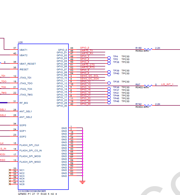
    Did you measure this timing on EVB? We measured these items and test result can't meet the spec of Table 5-9. GPIO Output Transition Times (VBAT = 3.3 V) and Table 5-10. GPIO Input Transition Time Parameters. I checked Table 4-4. Pin Attributes and Pin Multiplexing in datasheet. It mentioned that pin 46, 47 can be configured to GPIO or UART. Hence, I think that we shouldn't use Table 5-9 and Table 5-10 as its timing requirement. Am I wrong? Attached is our schematic for your reference. 

    Thanks.CC3220_Schematic.pdf

  • Hi Howard,

    I actually have not measured this myself. What is the discrepancy you are seeing? Timing may vary depending on how much capacitance is tied those pins. 

    Are you having any issues with the UART? Or just asking exploratory questions?

    On a side note, it is recommended to add 100K pull up to VBAT on pin46. It is also recommended to add 100K pull-up on pin47 to allow lowest current in Hibernate mode.

    In addition, you can request a thorough design review here if you haven't already. 

    BR,

    Seong

  • Hi Seong,

    I am Sercomm Oliver who is Howard's team member.

    We added a 100k pull high resistor but TX(3.3V side) pin still can't match the 2mA drive strength specification in GPIO. So we also change R90 from 1k to 100 ohm, then it can match the spec. 

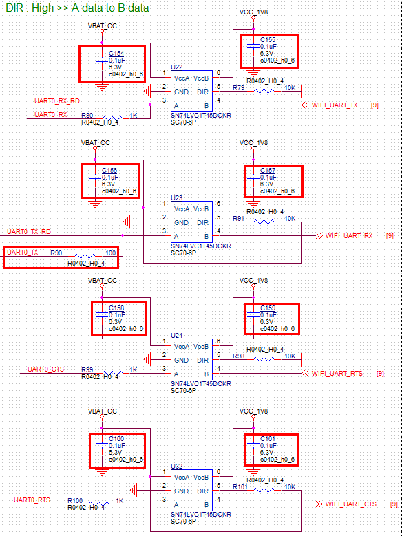
    Here is part of our UART Schematic below. UART0_TX_RD is connect to wifi module pin 46, UART0_TX is connect to Boot pin. 

    Could you please assist to review the UART Schematic if have any problem?

    BR,

    Oliver

  • Oliver,

    Note that on our LAUNCHCC3220MODASF reference design, we do not have 10k resistor, or R91, tied to 3V3 from the DIR pin.   

    We also do not have a 10k pull down resistor (R79).

    BR,

    Seong

  • Hi Seong,

    Is there any problem if we have R91 and R79?

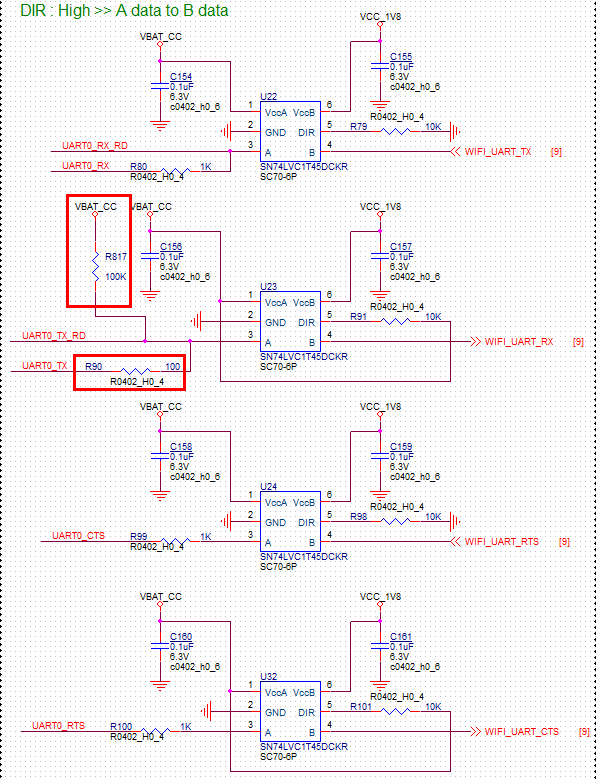
    In addition, could please assist to review the red place of picture have any problem or not.

    The R90 is connect to GPIO_01 of wifi module, and we change it from 1k to 100 ohm because of rising and falling time is higher than Wi-Fi module spec (around 40~50ns > 10ns).

    The R817 that we add is based on the reference schematic.

  • Oliver,

    I don't see any problems, but you can save BOM cost by eliminating them. 

    You previously mentioned that UART0_TX_RD is connected to pin 46 (GPIO01). Are you saying that UART0_TX is also connected to pin 46?

    Are you measuring the rise and fall time including the transceiver's rise and fall time?

    For specific questions regarding the SN74LVC1T45, it would be best to ask the experts at the Logic E2E Forums

    BR,

    Seong

  • Hi Seong,

    Are you saying that UART0_TX is also connected to pin 46?

    Yes, it is. The UART0_TX is also connected to pin46.

    Are you measuring the rise and fall time including the transceiver's rise and fall time?

    Yes, we have measured the rise and fall tome including transceivers rise and fall time, and is match with wifi module spec.

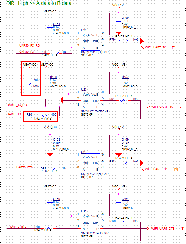
    Here is the UART schematic.

    Thanks for your help.

    BR

    Oliver

  • Oliver,

    I recommend you follow our reference design and replace R90 with a 0ohm. But to answer your question, no, I do not see any problems here.

    BR,

    Seong