This thread has been locked.

If you have a related question, please click the "Ask a related question" button in the top right corner. The newly created question will be automatically linked to this question.

CC3200-LAUNCHXL: ADC CH1 values unexpected

Part Number: CC3200-LAUNCHXL
Other Parts Discussed in Thread: CC3200

Hello,

I have configured the ADC with channels CH1, CH2 and CH3 and with an interrupt every 10ms to read the value of each of them and save it in a buffer.
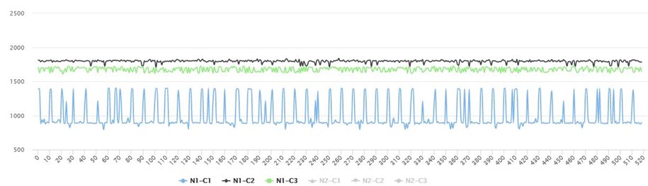
When I have 1000 readings for each channel, I export the values to display them graphically. The three channels are on the air without any connection, that is, they capture noise.
I have observed that CH1 has a lower average value than CH2 and CH3, around 850. In addition, peaks of 1400 values appear randomly in CH1 when they do not appear in CH2 and CH3.
 I have checked the configuration and everything seems to be correct. What can these peaks be due to??


Configuration:

ADCChannelEnable(ADC_BASE, ADC_CH_1);
ADCChannelEnable(ADC_BASE, ADC_CH_2);
ADCChannelEnable(ADC_BASE, ADC_CH_3);

// Enable ADC module
ADCEnable(ADC_BASE);

Code of interrupt:

if (ADCFIFOLvlGet(ADC_BASE, ADC_CH_1))
    bufferSamples[countsample].C1 = (((unsigned short) ADCFIFORead(ADC_BASE, ADC_CH_1) >> 2 ) & 0x0FFF);
if (ADCFIFOLvlGet(ADC_BASE, ADC_CH_2))
    bufferSamples[countsample].C2 = (((unsigned short) ADCFIFORead(ADC_BASE, ADC_CH_2) >> 2 ) & 0x0FFF);
if (ADCFIFOLvlGet(ADC_BASE, ADC_CH_3))
    bufferSamples[countsample].C3 = (((unsigned short) ADCFIFORead(ADC_BASE, ADC_CH_3) >> 2 ) & 0x0FFF);

Thanks.

  • The pines used are :

    // Configure PIN_58 for ADC0 ADC_CH1
        //
        PinTypeADC(PIN_58, PIN_MODE_255);

        //
        // Configure PIN_59 for ADC0 ADC_CH2
        //
        PinTypeADC(PIN_59, PIN_MODE_255);

        //
        // Configure PIN_60 for ADC0 ADC_CH3
        //
        PinTypeADC(PIN_60, PIN_MODE_255);

  • Hi,

    Is each channel left floating while you perform the measurements? In this case, the measurement data will be unpredictable.

    Do you see the same results if you were to connect the ADC channels to ground or another net with a known signal level?

    Regards,

    Michael

  • Hi Michael, thanks for your response.

    Yes, each channel is left in the air and the result should be noise but there is a big difference between CH1 and the other two channels CH2-CH3. CH2-CH3 are very similar and so CH1 should behave like that.

    If I connect all three channels to ground the result is ZERO on the graphs.

    If I connect a sinusoidal signal generator to all three channels the result is correct.


    But if I leave them on the air or connect them to a seismic motion sensor, channels CH2-CH3 work fine but in CH1  still shows those peaks.


    Very strange. Any sugestion??


  • Hi,

    The ADC pins of the CC32xx devices have input impedance and input capacitance that make them not behave as an ideal input. So you'll need to keep that in mind as you design your circuits and make your measurements.

    In particular, ADC pin 58 (CH1) has lower input impedance compared to the other two pins. Please take a look at Table 5-18 of the datasheet for the CC3220. This is a newer device than the CC3200, but the CC3200 and CC3220 have effectively the same ADC peripheral setup that the data is still comparable.

    Please also take a look at the CC32xx ADC appnote, as it has more details on how to design with and use the ADC and has info that may answer further questions.

    Regards,

    Michael