This thread has been locked.

If you have a related question, please click the "Ask a related question" button in the top right corner. The newly created question will be automatically linked to this question.

CC3220MOD: Application Program Load without external MCU

Part Number: CC3220MOD
Other Parts Discussed in Thread: UNIFLASH, CC3220SF, SYSCONFIG

TI Friends & Family,

We have a customer trying to program the CC3220MODSF module on their Communication Control Board with internally developed application.  They are trying to get the Wi-Fi module working without the use of their external MCU at this time so that they can run some basic signal strength tests using the external antenna and housing.  Currently they are trying to communicate to the module over the UART port.  This is J3 on design (I can send the schematics separately).  For connecting to PC using a FTDI TTL-232R-3V3 UART to USB cable (https://www.ftdichip.com/Support/Documents/DataSheets/Cables/DS_TTL-232R_CABLES.pdf).  They have tried both the UARTLOAD and UARTLOAD_FUNCITONAL_4WJ SOP configurations, but do not see any signals transmissions on the UART TX and RX signals.  Have tried connecting cable to a Putty Terminal as well as looking at the TX and RX signals on an Oscope.  One item to note from the schematics is that the nRESET signal is always pulled low on the board.  To easily get around this at a home office they have shorted nRESET signal connected to the JTAG connector J1 pin 10 to the +3.3V pin J1 pin 1.  Due to the 4.75K pull down on nRESET and the 1K pull on +3.3V this causes a voltage divider on the nRESET pin with a voltage of 2.7V.  Is +2.7V enough of pull the module out of reset?


Questions:

  1. Is there a recommend UART programming/debug cable for the module?
  2. Do we have a recommend JTAG debugger for the CC3220MODSDF?  Is that XDS like the LaunchPad?
  3. Is there a way to see if the CC3220 is not being held in reset?
  4. Do they need any signals other than the UART TX and RX to program the CC3220 over UART?
  5. They have also tried using UniFlash to load software over the FTDI cable but get an error message.  Looking at the log messages it appears the need for a specific TI debugger if that is correct?  Again, is that XDS like the Launchpad?

TY,

CY

  • Hi Chris,

    To answer your questions:

    1. The recommended UART programmer is the XDS110. This is what comes with every CC32xx launchpad, as well as other TI connectivity devices such as the 13xx and 26xx.

    2. The XDS110 is also a JTAG debugger, and is recommended for use with the CC32xx.

    3. In the datasheet, it is specified that nRESET must be held at 0.6V or below for reset to be asserted. But, it is not clear what is the minimum voltage to ensure a deasserted state. I will ask one of our HW engineers to comment.

    4. They also need to be able to toggle nRESET during programming. This can be handled through the XDS110

    5. Yes, the Uniflash GUI requires that you use either an XDS110 or an FTDI FT2232D device on your PC to connect, otherwise the auto-detect will fail. However you can use the Uniflash CLI to perform the flashing step as it has the option of manually specifying a COM port for use. See instructions in section 7 of the Uniflash Imagecreator User's Guide

    What I suggest they do if they're trying to test the RF characteristics is the following:

    1. Download and install the latest version of Radiotool: https://www.ti.com/tool/CC3XXXRADIOTEST

    2. Prepare a project in Uniflash Imagecreator following the guide here: https://dev.ti.com/tirex/explore/node?node=ABEoqU9o3snoxDcmIpW0EA__fc2e6sr__LATEST

    When adding the MCU image, please ensure they add the CC32xxSF image at /Source Files/Precompiled Binaries of their radiotool install

    3. Once the project is setup, right at the Burn/Program Image step, switch over to the Uniflash CLI to use their FTDI cable's COM port for programming.

    4. Once programming is complete, use the radiotool program following the guide here to test out the RF parameters needed:

    https://www.ti.com/lit/swru471

    Regards,

    Michael

  • Hi CY,

    Could you please share the customer's schematic? I will send you a request to be friends on E2E.

    BR,

    Seong

  • Thank you both Michael and Seong.  I will follow up with the schematic offline.  For now, your answers are spot-on and we certainly appreciate it.

    TY,
    Chris

  • Hi Chris,

    As mentioned in my email, the UART pins for flashing are pins 46 and 47. Each require 100k pull up resistors.

    I see in the schematic that they are using pins 48 and 49. This is the problem.

    BR,

    Seong

  • Seong,

    In fact, you are 100% correct.  And after looking more deeply into all of the information regarding the CC3220SF they have realized that they have pinned out the wrong UART for flashing the module.  Unfortunately without respinning the design at this time they cannot access pin 46 and 47 on the board.  Thankfully, they do plan on including the UART0 interface for flashing on the next PCB design. 


    So, long story short…that is why they have been hoping to flash their module using the JTAG interface and the XDS110.


    Unfortunately, they have not been able to use Uniflash to connect to even their LaunchPad over JTAG as we suggested they try firsthand.  That’s strange in my mind.


    They have been able to import an example project for the LaunchPad in CSS v10, but get the following error when they build the project.


    C:/ti/ccs1030/ccs/tools/compiler/ti-cgt-arm_20.2.5.LTS/bin/armobjcopy -O binary --only-section .text --only-section .const --only-section .cinit --only-section .resetVecs out_of_box_CC3220SF_LAUNCHXL_tirtos_ccs.out out_of_box_CC3220SF_LAUNCHXL_tirtos_ccs.bin

    C:/ti/simplelink_cc32xx_sdk_5_10_00_02/source/ti/drivers/net/imagecreator/bin/SLImageCreator.exe syscfg create_image --sdk_path C:/ti/simplelink_cc32xx_sdk_5_10_00_02 --json C:\Users\piercem2\workspace_v10\out_of_box_CC3220SF_LAUNCHXL_tirtos_ccs\MCU+Image/syscfg/ti_drivers_net_wifi_config.json --file C:\Users\piercem2\workspace_v10\out_of_box_CC3220SF_LAUNCHXL_tirtos_ccs\MCU+Image/syscfg/out_of_box_CC3220SF_LAUNCHXL_tirtos_ccs.sli --mcu  C:\Users\piercem2\workspace_v10\out_of_box_CC3220SF_LAUNCHXL_tirtos_ccs\MCU+Image/out_of_box_CC3220SF_LAUNCHXL_tirtos_ccs.bin

    INFO:root:FTDI not detected, trying XDS

    INFO:slbootloader.slbootloader:Connecting to device

    INFO:slbootloader.slbootloader:Power off

    INFO:slbootloader.slbootloader:Set break signal

    INFO:slbootloader.slbootloader:Power on

    makefile:183: recipe for target 'post-build' failed

    Traceback (most recent call last):

      File "<string>", line 5262, in <module>

      File "<string>", line 5258, in main

      File "<string>", line 5228, in cmdline

      File "<string>", line 4653, in command_sysconfig_create_image

      File "<string>", line 2498, in create_image_from_sysconfig

      File "<string>", line 1567, in connect_device

      File "W:\slbootloader\slbootloader.py", line 409, in connect_with_reset

      File "W:\slbootloader\slbootloader.py", line 271, in _expect_ack

      File "W:\slbootloader\slbootloader.py", line 302, in _read_data

    slbootloader.slbootloader.BootLoaderError:

    Error: SLImageCreator.exe: BootLoaderError, Timeout reading data

    SLImageCreator returned -1

    gmake[2]: [post-build] Error -1 (ignored)


    For this test they are using the integrated XDS that is part of the LaunchPad eval board.  With all of the default jumper connections for the JTAG and UART. 


    Seems to me since they are using a TI Launchpad it isn’t a design checklist issue with the PCB but maybe rather a power supply issue or something like that?  Seems more like a communications issue to me based on the error messages? 


    I know on the e2e forums you are very active in helping customers with similar problems, Seong.  Let me know what you think?


    Thanks,
    Chris

  • Hi Chris,

    The error that the customer is seeing in the build process is actually in the post-build imagecreator invocation. In newer versions of the SDK, we have integrated the UART bootloader functionality so that customers can build and persistently flash their CC32xx devices in one step. However, if there happens to be an error during this flashing process, it will appear as a build error.

    That being said, the actual compilation and linking stage was successful. So the customer can simply load that generated .out directly onto the CC32xx through JTAG. Of course, the same bootloader error will appear and so CCS will warn the customer that there are errors encountered in build, but this can be ignored - we will be loading the code through JTAG, and not UART.

    To load code through JTAG, the customer can simply click on the green JTAG debug button as per usual.

    Let me know if that doesn't work for the customer.

    Regards,

    Michael

  • Hi Michael,

    Customer was able to program the Lauchpad eval board with the Out of Box demo software using both the integrated XDS110 of the eval board and external XDS110 using JTAG.  For both of these test they used SOP = 000.  When testing with the external XDS110 they powered the Lauchpad using an external bench supply to remove the second USB connection to the PC.

     After this successful test they switched back to their board.  For this tested they removed R2 on their board which was pulling down the nRESET signal.  Removing this resistor made their board similar to the Lauchpad eval.  Using the same Out of Box demo software they tried Debugging their board using the same method used for the Launchpad with their external XSD110.  Everything seem like it worked initially, but then they get this error message:

     Cortex_M4_0: GEL Output:

    Memory Map Initialization Complete

    CS_DAP: Error connecting to the target: (Error -1170 @ 0x0) Unable to access the DAP. Reset the device, and retry the operation. If error persists, confirm configuration, power-cycle the board, and/or try more reliable JTAG settings (e.g. lower TCLK). (Emulation package 9.3.0.00042)


    They have tired lowering the JTAG clock to both 1 MHz and 100 KHz by modifying the CC3220SF.ccxml Target Configuration file but this did not seem to change anything.

     Is there something they are missing regarding the JTAG configuration on their board?  From my experience with this Error it seems still like a communications issue, maybe with their custom board.

    TY,
    CY

  • Hi Chris,

    Were they ever able to flash their custom board with over UART? It is very likely that their CC3220 is in production mode. In production mode, most debug options such as JTAG access is locked.

    The customer needs to flash their board at least once into development mode in order for the JTAG to be unlocked.

    If the customer doesn't have the ability to access UART at all, then they will  need to flash the SPI flash within the module directly. Instructions for doing so can be found in section 4 of the production line guide: www.ti.com/.../

    Note that you will be using the FLASH_SPI_* signals on the module, instead of wiring directly to the serial flash as per the diagram in that document.

    Regards,

    Michael

  • Hi Michael,

    No they have not been able to flash their custom board using the UART.  So I would suspect too that the module is still in production mode.

    They did bring out the 4 serial flash pins to test points that are shown in the product line app note that you referenced.  I've also referenced swra645 in addition to swra548.

    This is a little more complicated than they were expecting but they definitely want to exhaust all possibilities before they re-spin the board.

    I've sent some of our external SPI programmer recommendations.  I think the Total Phase Cheetah will work just fine for them.  (Your other e2e thread references).

    Let's keep this open for now until they have a chance to try the SPI programmer but so far, so good for the time being.

    Thanks again,
    Chris

  • Hi Chris,

    Thanks for the update. Yes, the Cheetah is what I use in the office to interface with the CC32xx serial flash, I appreciate you checking my other posts and providing that info to the customer.

    Let me know if they encounter any difficulties or need any further help.

    Regards,

    Michael

  • Michael et al,

    So, customer got their Cheetah SPI programmer and have connected up a header to the module.  They were able to program the module using the Total Phase software.  At least we think it programmed properly as they did not get any error messages during the flash process.  The software programmed using the SPI programmer was the Out of Box Demo .bin file created by CSS.  After programming the flash they tried to start up the JTAG debug connection using CSS, but got the same error message as before.  Shouldn't the Out of Box demo software put the Module into development mode?  If not, is there another demo project for the CC3220SF that enables development mode if the Out of Box demo does not?  Upon review of the CC3220SF Demos on Resource Center customer did not see anything demo project that specifically called this feature out.

     Any help you can provide with the creating the right software binary would be great.

    TY,

    CY

  • Hi CY,

    What was the precise process that the customer used to program their SPI flash?

    The out-of-box Uniflash project should indeed be putting their device into development mode. But just to clarify, do they see the expected output of the out of box example from their device?

    The steps the customer should be doing are the following:

    1. Download and install Uniflash

    2. In Uniflash, select the CC3220 launchxl device. Or, they can simply run the SLImageCreator.exe at simplelink/imagecreator/bin of their Uniflash install.

    3. In Uniflash, click on Manage Project ->Import a project from a zip file. Then go to examples/rtos/CC3220SF_LAUNCHXL/demos/out_of_box/uniflash and import the project

    4.  Once in the project view, click on burn -> save bin. Do note that this binary is different from the .bin generated by CCS. The customer needs to use the .bin provided through Uniflash, and not directly through CCS if they are flashing directly to the SPI flash

    5. Flash the .bin from step 4 onto the SPI flash.

    Please double-check and ensure that the customer is following those steps.

    Regards,

    Michael

  • Michael,

    Thanks for the updated instructions. 

    from customer "I saw that you were supposed to create the .bin file using Uniflash but I did not know how to do that.  I am just a hardware guy dabbling in software.  This morning I follow the Uniflash instructions and create a .bin file and was successfully able to flash it into the module. I am assuming it was a successful flash since I didn’t get any programming errors from the Total Phase Flash tool.  After flashing I disconnected the Cheetah box and removed my jumper that was holding the module in reset (I added a jumper to nRESET (pin35) on the module to make this step easier.).  I then turn off the board power and connected my XDS110 and set the SOP pins to 000.  Next I power up the board and tried to debug the Module using the XD110 JTAG interface and CSS. 

     Unfortunately I am still getting the same error message as before.

    CS_DAP: Error connecting to the target: (Error -1170 @ 0x0) Unable to access the DAP. Reset the device, and retry the operation. If error persists, confirm configuration, power-cycle the board, and/or try more reliable JTAG settings (e.g. lower TCLK). (Emulation package 9.3.0.00042)

     Is there a step that I am missing in CSS?  The steps that I am doing in CSS are I am clicking on the .out file found under the Binaries folder and then click on Green Bug icon in the tool bar."

    Let me know if there is something obvious we are still missing here?

    Thanks MIchael,

    Chris

  • Hi Chris,

    If the customer was successful in applying the OOB image to the device, then it should boot up into the out-of-box functionality. Can the customer confirm that their CC3220 is running the OOB code? That will allow us to tell if the flashing process worked for sure.

    There are some more debug tips that can be found in this thread:

    https://e2e.ti.com/support/wireless-connectivity/wi-fi-group/wifi/f/wi-fi-forum/717279/ccs-cc3220-for-cc3220r-production-line-the-gang-image-not-work-correctly

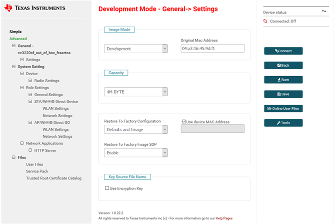
    One of them which might be applicable is the MAC address setting of the customer's Uniflash image. In development mode, you must provide the MAC address of the target device, for security reasons. Usually, this is auto-populated for you in Uniflash as it will auto-detect any connected CC3220 devices, but if the customer never could connect to Uniflash then they will need to provide that manually. This should be done in the general->settings view:

    Regards,

    Michael