This thread has been locked.

If you have a related question, please click the "Ask a related question" button in the top right corner. The newly created question will be automatically linked to this question.

SMARTRF06EBK: with CC2538 not able to read SPI data from MISO pin

Part Number: SMARTRF06EBK
Other Parts Discussed in Thread: CC2538, CC2530

Hello,

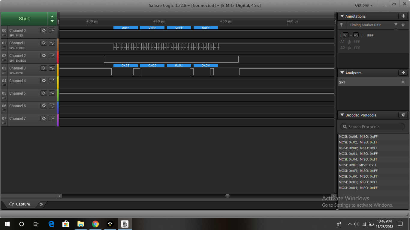
I have interfaced M95M01 EEPROM to my SmartRF06 board with CC2538, i am not able to read the data over MISO pin of SSI.

Though i am able to transmit data on MOSI pin and can view the data & chip select pin on logic analyzer below is my initialization. I have done EEPROM interface successfully on CC2530. now i am porting the same on CC2538. Below is my initialization for SSI

#define PIN_SSI_CLK GPIO_PIN_2
#define PIN_SSI_FSS GPIO_PIN_3
#define PIN_SSI_RX GPIO_PIN_4
#define PIN_SSI_TX GPIO_PIN_5

SysCtrlClockSet(false, false, SYS_CTRL_SYSDIV_32MHZ);

SysCtrlIOClockSet(SYS_CTRL_SYSDIV_32MHZ);

SysCtrlPeripheralEnable(SYS_CTRL_PERIPH_SSI0);

SSIDisable(SSI0_BASE);

SSIClockSourceSet(SSI0_BASE, SSI_CLOCK_PIOSC);

IOCPinConfigPeriphOutput(GPIO_A_BASE, PIN_SSI_CLK, IOC_MUX_OUT_SEL_SSI0_CLKOUT);

IOCPinConfigPeriphOutput(GPIO_A_BASE, PIN_SSI_FSS, IOC_MUX_OUT_SEL_SSI0_FSSOUT);

IOCPinConfigPeriphOutput(GPIO_A_BASE, PIN_SSI_TX, IOC_MUX_OUT_SEL_SSI0_TXD);

IOCPinConfigPeriphInput(GPIO_A_BASE, PIN_SSI_RX, IOC_SSIRXD_SSI0);

GPIOPinTypeSSI(GPIO_A_BASE, (PIN_SSI_CLK | PIN_SSI_FSS | PIN_SSI_RX | PIN_SSI_TX));

SSIConfigSetExpClk(SSI0_BASE, SysCtrlIOClockGet(), SSI_FRF_MOTO_MODE_3, SSI_MODE_MASTER, SysCtrlClockGet()/8, 8);
SSIEnable(SSI0_BASE);

help me if i am wrong with initialization or any other issue.

Thank You,

Regards,

Akshay B


  • Do you see clock signal on SCLK pin?

  • Hi YiKai,

    on logic analyzer, i am not able to see Clock when data is receiving but able to see the clock while transmitting.

    Thank you.
  • When receiving data, the SCLK should be there.
  • i have used SSIDataGet() API from driver library of SSI to receive data

    uint32 status;
    SSIDataGet(SSI0_BASE, &status);
  • Hi akshay,

    As YK mentioned, the SCLK should be active when you are either receiving or transmitting data.
    Please share screenshots of your logic analyzer when you transmit and receive for further analysis. Additional code snippets help as well.

    Have you verified that the spi example in the foundation firmware works ( www.ti.com/.../CC2538-SW )? I would recommend starting there and modifying it as applicable for your project.


    Regards,
    Toby

  • Hi Toby,

    I have attached the logic analyzer screenshot for SPI example in the foundation firmware. Here i am able to send data 's' 'p' 'i' as you can see from SPI send screenshot 1 & SPI send screenshot 2 image.

    For receiving code i am not able to see any thing no clock, no chip select as you can see in SPI Receive Screen shot image. Though i am able to see the receive data on UART in i shot PA4 & PA5  pinon board.

    SPI send screenshot 1

    SPI send screenshot 2

    SPI Receive Screen shot

  • That's the expected behavior. Since MOSI is shorted to MISO, the 's', 'p', and 'i' are received at the same time they're sent (as you can see the MISO activity on the first two screenshots). In this case, SSIDataGet will find that the FIFO has data and read from it.

    Please verify whether you see similar activity on MISO when you are interfacing with the other device.
  • Hi Toby,

    Sorry for late reply, as i was testing but still not able to receive the data on MISO pin, below is my initialization can you check and let me know if the initialization for SPI master is correct

    SysCtrlClockSet(false, false, SYS_CTRL_SYSDIV_32MHZ);

    SysCtrlIOClockSet(SYS_CTRL_SYSDIV_32MHZ);
    SysCtrlPeripheralEnable(SYS_CTRL_PERIPH_SSI0);
    SSIDisable(SSI0_BASE); // Disable SSI function before configuring module
    SSIClockSourceSet(SSI0_BASE, SSI_CLOCK_PIOSC); // Set IO clock as SSI clock source

    IOCPinConfigPeriphOutput(GPIO_A_BASE, PIN_SSI_CLK, IOC_MUX_OUT_SEL_SSI0_CLKOUT);
    IOCPinConfigPeriphOutput(GPIO_A_BASE, PIN_SSI_TX, IOC_MUX_OUT_SEL_SSI0_TXD);
    IOCPinConfigPeriphInput(GPIO_A_BASE, PIN_SSI_RX, IOC_SSIRXD_SSI0);

    GPIOPinTypeSSI(GPIO_A_BASE, (PIN_SSI_CLK | PIN_SSI_RX | PIN_SSI_TX));

    SSIConfigSetExpClk(SSI0_BASE, SysCtrlIOClockGet(), SSI_FRF_MOTO_MODE_3, SSI_MODE_MASTER, SysCtrlClockGet()/16, 8);
    SSIEnable(SSI0_BASE);
    GPIODirModeSet(GPIO_A_BASE, GPIO_PIN_1, GPIO_DIR_MODE_OUT); //chip select pin for M95M01
    GPIOPinWrite(GPIO_A_BASE, GPIO_PIN_1, 0xFF);
  • Since you're controlling the chip select pin in the application (PA1), make sure that you set it low before initiating an SSI transfer.

    Please send us logic analyzer screenshots when you try interfacing to your device.
    It may also be useful to compare those screenshots with logic analyzer screenshots when you interfaced with the CC2530 in this post: e2e.ti.com/.../734024
  • Hi Toby,

    I have taken care of the Chip Select pin while transmitting & receiving the data, still i am not able to receive it.

    As you can see in the attached logic analyzer screenshot, i am sending out the commands & address to the EEPROM chip which should return the data at that address but it is not showing anything on MISO pin neither it is showing clock. i will share the receive code as well.

    GPIOPinWrite(GPIO_A_BASE, GPIO_PIN_1, 0x00);
    SSIDataPut(SSI0_BASE, CMD_READ);
    SSIDataPut(SSI0_BASE, ((page_start_address>>16) & 0xFF));
    SSIDataPut(SSI0_BASE, ((page_start_address>>8) & 0xFF));
    SSIDataPut(SSI0_BASE, (page_start_address & 0xFF));
    while(SSIBusy(SSI0_BASE));

    SSIDataGet(SSI0_BASE, &status);

    GPIOPinWrite(GPIO_A_BASE, GPIO_PIN_1, 0xFF);

  • Hello,

    The issue was that as i was not using dummy send SSIDataPut to receive the data using SSIDataGet. Also need to apply a delay of 50 SysCtrlDelay(50) after SSIDataGet for proper output.

    Thank you.
  • Hi Toby,

    I am able to see the data read from the slave(EEPROM) on logic analyzer but the variable in my code is not updating as per the data, it is showing 0X000000 as it is an int.

    Attaching the screenshot for my logic analyzer. here you can see data that is read 0x78 0x00 0x00 0x00

  • Are you attempting to read and store 4 bytes from the receive fifo into one int? If so, you may be overwriting the int.

    In your SPI initialization, you are using 8 bit data width, so each SSIDataGet will retrieve one byte from the receive fifo.
    If you'd like to get all 4 bytes, try something like this:

    uint32_t dummyData = 0;
    uint32_t rxByte[4];
    
    SSIDataPut(SSI0_BASE, &dummyData);
    SSIDataGet(SSI0_BASE, &rxByte[0]);
    
    SSIDataPut(SSI0_BASE, &dummyData);
    SSIDataGet(SSI0_BASE, &rxByte[1]);
    
    SSIDataPut(SSI0_BASE, &dummyData);
    SSIDataGet(SSI0_BASE, &rxByte[2]);
    
    SSIDataPut(SSI0_BASE, &dummyData);
    SSIDataGet(SSI0_BASE, &rxByte[3]);

  • Hi toby,

    I m doing the same below, is my code

    uint32_t one;
    uint32_t two;
    uint32_t three;
    uint32_t four;

    GPIOPinWrite(GPIO_A_BASE, GPIO_PIN_2, 0x00);
    SSIDataPut(SSI0_BASE, MSB);
    SSIDataPut(SSI0_BASE, LSB);

    SSIDataPut(SSI0_BASE, ADE7953_READ); //Send command to begin readout
    while(SSIBusy(SSI0_BASE))
    {
    }

    SSIDataPut(SSI0_BASE, 0x00);
    SSIDataGet(SSI0_BASE, &one);
    SSIDataPut(SSI0_BASE, 0x00);
    SSIDataGet(SSI0_BASE, &two);
    SSIDataPut(SSI0_BASE, 0x00);
    SSIDataGet(SSI0_BASE, &three);
    SSIDataPut(SSI0_BASE, 0x00);
    SSIDataGet(SSI0_BASE, &four);
    SysCtrlDelay(50);
    GPIOPinWrite(GPIO_A_BASE, GPIO_PIN_2, 0xFF);

    still i am not able to receive data in individual variable.
  • need to add SSIDataGetNonBlocking before spi data get.

    while(SSIDataGetNonBlocking(SSI0_BASE, temp_arr))
    {
    }