This thread has been locked.

If you have a related question, please click the "Ask a related question" button in the top right corner. The newly created question will be automatically linked to this question.

TIDC-CC2650STK-SENSORTAG: DevPack TIDA-00650 (Thermocouple Sensor) with Z-Stack_Home_1.2.2a - GPIO Board configuration

Part Number: TIDC-CC2650STK-SENSORTAG
Other Parts Discussed in Thread: TIDA-00650, CC2650STK, Z-STACK

Hello everyone,

PREABLE: thread https://e2e.ti.com/support/wireless-connectivity/zigbee-and-thread/f/158/p/854841/3161491#3161491 has been solved!

The problem was due to the incorrect procedure for reading the voltage data (RDATA), this did not work because I executed two instructions as below:

// RDATA(): Read data command
commandSPI = 0x10; 
bspSpiWrite(&commandSPI, sizeof(commandSPI))
// Read data (24 bit) VoltagePT100[0] = 0x00; VoltagePT100[1] = 0x00; VoltagePT100[2] = 0x00; bspSpiWriteRead(VoltagePT100, sizeof(VoltagePT100[0]), sizeof(VoltagePT100))

because the bsp_spi library internally manages the pins of the SPI interface and...so it happened that at the end of the execution of the first instruction (RDATA) as the chip-select is brought to the high value:

nCS_ADC --> HIGH

the transaction was concluded!

Instead performing in a single statement works:

/* Step 6 - RDATA: Read data: command + read data */ 
VoltagePT100[0] = 0x10; // RDATA() command: write1 byte (command = 0x10), Read data: read 3 bytes (data)
VoltagePT100[1] = 0x00;
VoltagePT100[2] = 0x00;

bspSpiWriteRead(VoltagePT100, sizeof(VoltagePT100[0]), sizeof(VoltagePT100))  // data (24 bits): MS byte of data + Central Byte of data + LS byte of data

CURRENT ISSUE: how to configure the board Devpack PINs?

I don't understand why as soon as the TIDA-00650 board is connected via devpack to the CC2650STK board I see a continuous consumption of about 5 mA, when the board is not powered!

My PIN configuration below:

Called from main.c:

PIN_Config BoardGpioInitTable[] = {
Board_LED1 | PIN_GPIO_OUTPUT_EN | PIN_GPIO_LOW | PIN_PUSHPULL | PIN_DRVSTR_MAX, /* LED initially off */
Board_LED2 | PIN_GPIO_OUTPUT_EN | PIN_GPIO_LOW | PIN_PUSHPULL | PIN_DRVSTR_MAX, /* LED initially off */
Board_KEY_LEFT | PIN_INPUT_EN | PIN_PULLUP | PIN_IRQ_BOTHEDGES | PIN_HYSTERESIS, /* Button is active low */
Board_KEY_RIGHT | PIN_INPUT_EN | PIN_PULLUP | PIN_IRQ_BOTHEDGES | PIN_HYSTERESIS, /* Button is active low */
Board_RELAY | PIN_INPUT_EN | PIN_PULLDOWN | PIN_IRQ_BOTHEDGES | PIN_HYSTERESIS, /* Relay is active high */
Board_MPU_INT | PIN_INPUT_EN | PIN_PULLDOWN | PIN_IRQ_NEGEDGE | PIN_HYSTERESIS, /* MPU_INT is active low */
Board_TMP_RDY | PIN_INPUT_EN | PIN_PULLUP | PIN_HYSTERESIS, /* TMP_RDY is active high */
Board_BUZZER | PIN_GPIO_OUTPUT_EN | PIN_GPIO_LOW | PIN_PUSHPULL | PIN_DRVSTR_MAX, /* Buzzer initially off */
//Board_MPU_POWER | PIN_GPIO_OUTPUT_EN | PIN_GPIO_HIGH | PIN_PUSHPULL | PIN_DRVSTR_MAX, /* MPU initially on */
Board_MPU_POWER | PIN_GPIO_OUTPUT_EN | PIN_GPIO_LOW | PIN_PUSHPULL | PIN_DRVSTR_MIN, /* MPU initially off */
//Board_MIC_POWER | PIN_GPIO_OUTPUT_EN | PIN_GPIO_HIGH | PIN_PUSHPULL | PIN_DRVSTR_MAX, /* MIC initially on */
Board_MIC_POWER | PIN_GPIO_OUTPUT_EN | PIN_GPIO_LOW | PIN_PUSHPULL | PIN_DRVSTR_MIN, /* MIC initially off */
Board_SPI_FLASH_CS | PIN_GPIO_OUTPUT_EN | PIN_GPIO_HIGH | PIN_PUSHPULL | PIN_DRVSTR_MIN, /* External flash chip select */
Board_SPI_DEVPK_CS | PIN_GPIO_OUTPUT_EN | PIN_GPIO_HIGH | PIN_PUSHPULL | PIN_DRVSTR_MIN, /* DevPack chip select */
Board_AUDIO_DI | PIN_INPUT_EN | PIN_PULLDOWN, /* Audio DI */
Board_AUDIODO | PIN_GPIO_OUTPUT_EN | PIN_GPIO_HIGH | PIN_PUSHPULL | PIN_DRVSTR_MIN, /* Audio data out */
Board_DP2 | PIN_INPUT_EN | PIN_NOPULL,                                                                                            /* DevPack - nDRDY_ADC - NOT USED */
Board_DP1 | PIN_GPIO_OUTPUT_EN | PIN_GPIO_LOW | PIN_PUSHPULL | PIN_DRVSTR_MAX,
// Board_DP0 | PIN_GPIO_OUTPUT_EN | PIN_GPIO_LOW | PIN_PUSHPULL | PIN_DRVSTR_MAX,     /* DevPack - LED (green) - NOT USED */
Board_DP3 | PIN_GPIO_OUTPUT_EN | PIN_GPIO_LOW | PIN_PUSHPULL | PIN_DRVSTR_MAX,        /* DevPack - TIDA-00650 PWR_UP_CHIP*/
Board_DP4_UARTRX | PIN_INPUT_EN | PIN_PULLDOWN,                                                                      /* DevPack */
Board_DP5_UARTTX | PIN_INPUT_EN | PIN_PULLDOWN,                                                                       /* Devpack */
//Board_DEVPK_ID | PIN_INPUT_EN | PIN_NOPULL,                                                                                 /* Device pack ID - external PU */

PIN_TERMINATE
};

then in sensortagapp.c I configure the following pins to check the TIDA-00650 board:

#if defined(TIDA_00650)
// PIN table for TIDA-00650
static PIN_Config TIDA00650_PinTable[] =
{
// Devpack interface
Board_DP3 | PIN_GPIO_OUTPUT_EN | PIN_GPIO_LOW | PIN_PUSHPULL | PIN_DRVSTR_MAX,/* DevPack : TIDA-00650 | PWR_UP_CHIP --> LOW */
Board_DP2 | PIN_INPUT_EN | PIN_NOPULL, /* DevPack : TIDA-00650 | nDRDY_ADC --> LOW , NOT USED */
PIN_TERMINATE /* Terminate list */
};

What could be the problem? I want to get the following behavior:

at expire of TIMEOUT:

  1. PIN_setOutputValue(hGpioPin, Board_DP3, 1);                   // TIDA-00650 | PWR_UP_CHIP --> HIGH
  2. Configure the ADC registers and read the voltage values...
  3. PIN_setOutputValue(hGpioPin, Board_DP3, 0);                   // TIDA-00650 | PWR_UP_CHIP --> LOW

Before and after TIDA-00650 is not powered (by pin "Board_DP3") and therefore should not consume anything!?

thank you everyone!

  • I think it’s normal to see such power consumption when debugger is connected. Why do you need to measure power consumption with debugger connected?

  • Hi YiKai, in fact I'm not interested in monitoring energy consumption when the debugger is connected to the sensor node, absolutely no...

    I have seen the power consumption of 5 mA in the following conditions:

    nodo sensore (CC2650STK) + Wireless Thermocouple Sensor Transmitter DevPack (TIDA-00650) + CR2032 BATTERY 

    Thanks for the reply!

  • Hi,

    Is Z-Stack running at this point?

    Have you tried running only the driver code?

    Regards,
    Toby

  • I think I misunderstand your question in the beginning. I agree with Toby. You should check power consumption running only driver code first.

  • Ok, what's the easiest way to do it?

    for example: insert the driver functionalities for reading from TIDA-00650 board in the main.c file and download just the "SensorTag - SensorTag" on target CC2650STK?

    thanks

  • I suppose you should add TIDA-00650 sensor init code inside SensorTagApp_initialization() and create an event in SensorTagApp_process() to do SPI  TIDA-00650 sensor reading.

  • One option is to define your own task function, sensorTask, and then in main() use Task_construct(&myTask, sensorTask, stackParams, NULL);

    Then in sensorTask, perform some sequence interfacing with the TIDA (eg read, sleep, read, sleep, ... etc).

  • Hi everyone,

    I learned that: even using the basic firmware version "zstack_home_1_02_02a_44539", adding to this only the initialization instruction of the SPI bus:

    // Setup SPI Controller Interface (TIDA-00650)
    bspSpiOpen();

    when the TIDA-00650 devpack is connected to the CC2650STK sensor node...I see an energy consumption of 5 mA (about)!

    ...and this happens even when I connect the CC-DEBUG-DEVPACK.

    Instead if I unplug the devpack TIDA-00650 I no longer see this energy consumption!

    The problem seems to be due to the configuration of the PINs related to SPI interface. If I don't initialize the SPI bus I don't see this energy consumption (even when TIDA-00650 or CC-DEBUG-DEVPACK is connected to CC2650STK)!

    Thanks!

  • I don't have this TIDA-00650 devpack to test so I can only suggest you to use scope to check IO status to see how to fix it.

  • - To be sure how things are connected, is it possible to post a couple of pictures showing exactly how the boards you are using are connected to each other?

    - Is it possible to simplify the software part some my just running the SPI examples in TI-RTOS? It's easier to try to figure out hardware related setup issues using as simple as possible software since it's a lot easier to debug. 

  • Hi TER,

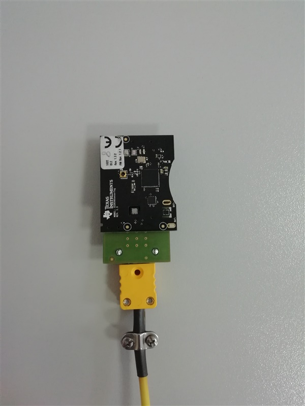
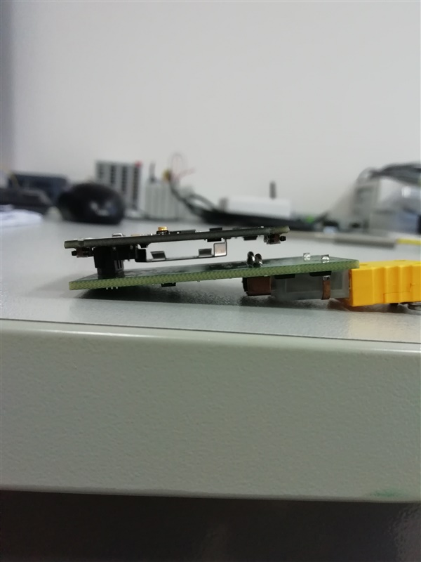
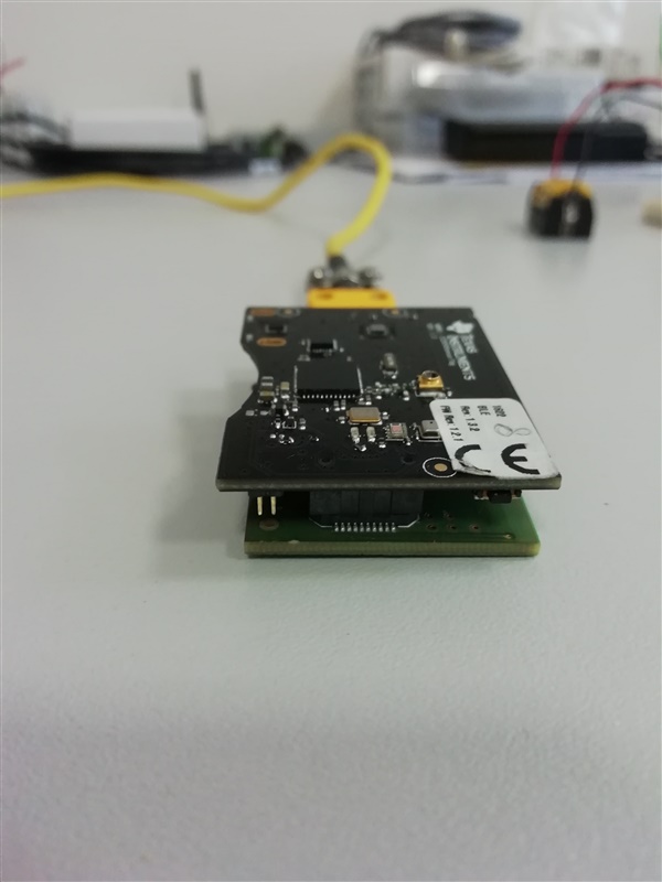
    sorry if I didn't answer right away. Attached you can see how the two cards are connected.

    Now I am starting to debug again to understand what happens, however the clear aspect is that it seems to be a configuration problem of the I/O pins...

    Since the excessive consumption of 5 mA (continuous) is there when I initialize the SPI interface (bspSpiOpen ()) and, the pins of the SPI interface are these::

    /* SPI configuration structure, describing which pins are to be used */
    const SPICC26XX_HWAttrs spiCC26XXDMAHWAttrs[CC2650_SPICOUNT] = {
        {   /* SENSORTAG_CC2650_SPI0 */
            .baseAddr = SSI0_BASE,
            .intNum = INT_SSI0,
            .defaultTxBufValue = 0,
            .powerMngrId = PERIPH_SSI0,
            .rxChannelBitMask = 1<<UDMA_CHAN_SSI0_RX,
            .txChannelBitMask = 1<<UDMA_CHAN_SSI0_TX,
            .mosiPin = Board_SPI0_MOSI,
            .misoPin = Board_SPI0_MISO,
            .clkPin = Board_SPI0_CLK,                                               // Changed (for TIDA-00650)
            //.clkPin = Board_SCLK_TDI,
            .csnPin = Board_DP1                                                     // Changed (for TIDA-00650)
            //.csnPin = PIN_UNASSIGNED     /* Note: External flash uses SPI0 */
        }
    };

    that is:

    CS     --> Board_DP1

    SCLK --> Board_SPI0_CLK

    MISO --> Board_SPI0_MISO

    MOSI --> Board_SPI0_MOSI

    DRDY --> Board_DP2 

    Note. Board_DP2 is configured as: Board_DP2 | PIN_INPUT_EN | PIN_NOPULL:

    #if defined(TIDA_00650)
    // PIN table for TIDA_006500 MGMT AND SPI Interface
    static PIN_Config TIDA00650_PinTable[] =
    {
      // TIDA_00650 MGMT
      Board_DP0 | PIN_GPIO_OUTPUT_EN | PIN_GPIO_LOW | PIN_PUSHPULL | PIN_DRVSTR_MAX,/* DevPack : TIDA-00650 | LED (green) --> OFF */
      Board_DP3 | PIN_GPIO_OUTPUT_EN | PIN_GPIO_LOW | PIN_PUSHPULL | PIN_DRVSTR_MAX,/* DevPack : TIDA-00650 | PWR_UP_CHIP --> LOW */
      // SPI Interface (just DRDY pin)
      Board_DP2 | PIN_INPUT_EN | PIN_NOPULL, 
      PIN_TERMINATE /* Terminate list */
    };

    does that mean the problem is on these pins !? Some ideas, suggestions...

    thank you very much for your support!

  • Hi to everyone,

    I have a few news of my issue, but its behavior is strange...if I use this PIN configuration of SPI interface:

    /* SPI configuration structure, describing which pins are to be used */
    const SPICC26XX_HWAttrs spiCC26XXDMAHWAttrs[CC2650_SPICOUNT] = {
        {   /* SENSORTAG_CC2650_SPI0 */
            .baseAddr = SSI0_BASE,
            .intNum = INT_SSI0,
            .defaultTxBufValue = 0,
            .powerMngrId = PERIPH_SSI0,
            .rxChannelBitMask = 1<<UDMA_CHAN_SSI0_RX,
            .txChannelBitMask = 1<<UDMA_CHAN_SSI0_TX,
            .mosiPin = Board_SPI0_MOSI,
            .misoPin = Board_SPI0_MISO,
            .clkPin = Board_SPI0_CLK,       // Changed  (TIDA-00650)
            //.clkPin = Board_SCLK_TDI,    // Not used (TIDA-00650)
            //.csnPin = Board_DP1              // Commented  (TIDA-00650)  --> By setting PIN "Board_DP1" it works but sees a consumption of 5 mA about (continous)
            .csnPin = PIN_UNASSIGNED     /* Note: External flash uses SPI0 */
        }
    };

    by setting as CS (chip-select):

    .csnPin = PIN_UNASSIGNED     /* Note: External flash uses SPI0 */

    instead of using the Board_DP1 pin, as I would have expected!...IT WORKS!!! AND THERE IS NO POWER CONSUMPTION OF 5 mA...BUT WHY???

    from the schematic, you can see the connection diagram of connector J2 for CC2650STK and TIDA-00650:

    TIDA-00650:

    CC2650STK:

    Thanks a lot again!

  • I don't have the full code base in front of me: Which DIOs are Board_DP1 and Board_DP2 mapped to? 

  • Hi TER, 

    Board_DP1 --> DIO_24

    Board_DP2 --> DIO_23

  • I sent a mail to the person that has made the TI design. His response was the following:

    "As far as I remember the SCLK_ADC signal (pin 5 in screenshot below) was wrongly routed on the DEV_PACK connector. We had to modify Board_SPI0_CLK from IOID_17 to IOID_11."

    When I look at the schematic I can't see why DP1 should cause an issue with the original code but most likely I must overlook something. 

  • Hello,

    as mentioned, SCLK_ADC goes to DIO11 and not to DIO17.

    Did this solve your problem?

    Regards, Thomas

  • Hi Thomas and TER,

    the problem/doubt is related to CS_ADC pin and not to SCLK_ADC pin: seeing the schematic of CC2650STK and TIDA-00650, the Board_DP1 (DIO_24) PIN is connected to nCS_ADC PIN of TIDA-00650.

    But how does CC2650STK communicate correctly with the TIDA-00650 board if this Board_DP1 is unassigned into SPI configuration structure:

    /* SPI configuration structure, describing which pins are to be used */
    const SPICC26XX_HWAttrs spiCC26XXDMAHWAttrs[CC2650_SPICOUNT] = {
        {   /* SENSORTAG_CC2650_SPI0 */
            .baseAddr = SSI0_BASE,
            .intNum = INT_SSI0,
            .defaultTxBufValue = 0,
            .powerMngrId = PERIPH_SSI0,
            .rxChannelBitMask = 1<<UDMA_CHAN_SSI0_RX,
            .txChannelBitMask = 1<<UDMA_CHAN_SSI0_TX,
            .mosiPin = Board_SPI0_MOSI,    // DIO_19 - (connect to TIDA-00650 SPI)
            .misoPin = Board_SPI0_MISO,    // DIO_18 - (connect to TIDA-00650 SPI)
            .clkPin = Board_SPI0_CLK,      // DIO_11 - (connect to TIDA-00650 SPI)
            //.clkPin = Board_SCLK_TDI,    // DIO_17 - Not used (TIDA-00650)
            //.csnPin = Board_DP1          // DIO_24 - Commented  (TIDA-00650) --> By setting PIN "Board_DP1" it works but sees a consumption of 5 mA about (continous)
            .csnPin = PIN_UNASSIGNED     /* Note: External flash uses SPI0 */
        }
    };

    By default:

    .csnPin = PIN_UNASSIGNED     /* Note: External flash uses SPI0 */

    In my case I also use this chip-select pin configuration and it works, but I want to understand why?

    Another strange thing is that even using this chip-select pin configuration:

    .csnPin = Board_DP1          // DIO_24 - Commented  (TIDA-00650) --> By setting PIN "Board_DP1" it works but sees a consumption of 5 mA about (continuously)

    Works the same way...but sees a consumption of 5 mA (continuously)