This thread has been locked.

If you have a related question, please click the "Ask a related question" button in the top right corner. The newly created question will be automatically linked to this question.

LAUNCHXL-CC1352P: DIO16 & DIO17 pins cannot be used as UART

Part Number: LAUNCHXL-CC1352P
Other Parts Discussed in Thread: SYSCONFIG, , Z-STACK

I have a CC1352P-2 LaunchPad, Simplelink_cc13x2_26x2_sdk version 4.10.0.78, My project is based on the zed_sw example project.

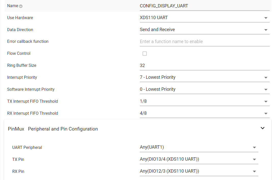
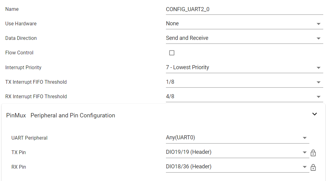
I configured UART2 to use DIO16 for TX and DIO17 for RX. I configured this UART using SysConfig. I looked in BoardGpioInitTable[] in ti_drivers_config.c and the UART appears there and is correctly configured.

The problem is this UART is not working. I have a logic analyzer hooked up to DIO16 and DIO17 and I see nothing. My code is using the UART driver. My code works with UART1, but I want to use UART1 for debugger output. That's why I'm using UART2 to communicate serially with an external device.

I have a Launchpad without TDO and TDI.jumpers. The user's guide for the Launchpad says that DIO16 and DIO17 are available for use if the TDO/TDI jumpers are not present.

Is there something else I need to do to configure DIO16 and DIO17 for use as UART2?

Thanks,

Tim

  • Hi Tim,

    DIO16 and DIO17 are reserved on the LAUNCHXL-CC1352P for JTAG TDO/TDI operation through the XDS110 Debugger.  Have you removed the corresponding jumper pins and modified your target configuration file (ccxml) for 2-pin debug?  http://dev.ti.com/tirex/explore/node?node=ALFqIj4dX6S.TZRERoSphA__FUz-xrs__LATEST 

    Can you also share how/where UART2 is initialized and used inside zed_sw?

    Regards,
    Ryan

  • Hi Ryan,

    The TDO and TDI jumpers are removed (in fact, the board came without these jumpers installed). The ccxml file is configured for "cJTAG (1149.7) 2-pin advanced modes".

    I have a TI-RTOS task that initializes UART2 (using UART_init() and UART_open()), then enters a loop that sends a request  (using UART_write()) and reads the response (using UART_read()) then sleeps for 10 seconds (using Task_sleep), wakes up and does it again. The device I'm communicating with over the UART is a PLC.

    I did some more googling. Someone mentioned that you have to remove resistors on TDI and TDO lines. Do you think that's it?

    BTW, my Launchpad says HW Rev B, SW SDK 2.40 on a label on the back of the board.

    Tim

  • Ryan, here is more info.

    Previously I was using SDK 3.20.0.68. At that time I configured the second UART with RX=DIO18 and TX=DIO19. This was before SysConfig, so I configured the second UART by adding RX and TX entries in BoardGpioInitTable[] .  This worked without problems.

    A couple of days ago I upgraded to SDK 4.10.0.78. This SDK has SysConfig so I don't need to directly edit tables anymore. I used SysConfig to configure the second UART with RX=DIO17 and TX=DIO16, as I described in my original post. But it doesn't work.

    Since I had the second UART working with before the upgrade, I decided to go back to using the pins I used then. So using SysConfig I configured the second UART to use RX=DIO18 and TX=DIO19. But using these pins don't work either.


    Are you aware of problems with SysConfig? Before the upgrade, when I edited BoardGpioInitTable[] directly, these pins worked just fine with the second UART.


    In SysConfig I see this:


    UART was already enabled and it's configured like this (these are the default settings, I didn't change anything):


    UART2 was there but was disabled, so I added it using the + sign, and configured like this:

    So did I configure incorrectly?

    "Use Hardware" is None. The only other choice is XDS100 UART. I don't think I want that since I'm not using this port with the debugger.

    "UART Peripheral" defaulted to Any(UART0). The only other choice is Any(UART1), but that's already used by the first UART so I don't think I want that.

    I selected TX = DIO19 and RX = DIO18,


    Questions:

    What's the difference between Any(UART0) and Any(UART1)?

    The SDK has 2 drivers, UART and UART2 (the old SDK had UART only). What's the difference?

    Why are there 2 drivers?

    The second UART is named UART2. Does it work with the UART driver? Do I have to use the UART2 driver? 

    Why are there 2 drivers?


    As I said, the second UART worked just fine with the old SDK using the UART driver.


    Please help. I have to get this working.


  • Hey Tim,

    The resistors in question only connect to the Boosterpack Headers and should not affect UART communication.  Have you tried using UART2 with different DIO pins, or experimented with UART1 using DIO16/17?  Are you able to get UART2 to work outside of a Z-Stack project?  Debugged to confirm the pin states and proper function execution?  This testing could help us locate the source of the issue.  The LaunchPad revision you are using is the latest offered.

    Edit: Thank you for providing the second thread, I will loop in a SysConfig expert to help comment based on your latest information.

    Regards,
    Ryan

  • Ryan I solved this.

    In SysConfig, UART2 is NOT the second UART as I thought. I think UART2 is intended for use with the UART2 driver (not the UART driver).

    The solution for me was to remove my configuration from the UART2 section and instead add a second UART to the UART section of SysConfig and configure it to use DIO16 and DIO17 pins. I also tried DIO18 and DIO19 and they worked too.

    Note to other readers of this post: to use DIO16 and DIO17 pins you have to remove the TDO and TDI jumpers and configure your target configuration file (ccxml) for cJTAG 2-pin debug. My Launchpad came without these jumpers and my ccxml was already configured for 2-pin debug. You don't have to remove any resistors from the board.

    Tim