This thread has been locked.

If you have a related question, please click the "Ask a related question" button in the top right corner. The newly created question will be automatically linked to this question.

CC2520: Communication disrupts at higher transmission power

Part Number: CC2520
Other Parts Discussed in Thread: CC2590, CC2591

Hi team,

Can you have a look at the following customer issue? Please let me know if you need schematics, layout or further information.

We currently have a problem with 2 TI-Zigbee-ICs:

And unfortunately currently have no starting point where to look further....

- CC2520 Transceiver Zigbee
- CC2590 Frontend

Register settings schematic and layout are exactly according to application-notes.
We have no temperature compensation of the transmit power by the software.

Problem:

Modules work perfect as long as the transmitting power is below 4dBm.
If you increase the transmit power (@transmit power register) no communication is possible.
Increasing the temperature of the Module makes communication possible temporarily.

Thank you,

Franz

  • Hi Franz, 

    Can you describe in greater detail what the team is seeing? Are they losing all signal entirely, or is the output noisy/corrupted? Have they measured if the signal stops at the transceiver or the range extender? How warm are they heating the module when they see it operating correctly? Any additional files would be helpful, but I think we need a greater description of the behavior observed before we can start to make sense of this.

    Best,

    Nate

  • Hi Nate,

    Please find additional info below:

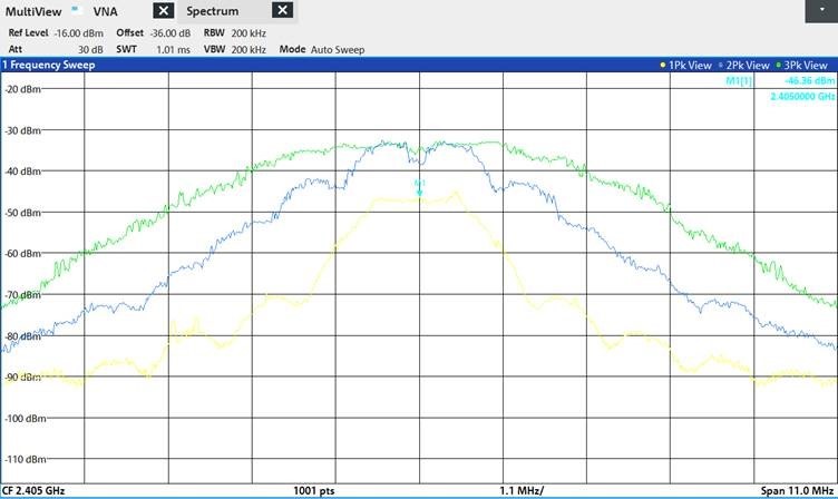
    Yellow: CC2520 with maximum power(F7) at 20°C Always works
    Blue: CC2520+2590 with high power(F9) (after front end) at 20°C Works when Temp>20°C
    Green: CC2520+2590 with max power(F7) (after frontend) at 20°C Works when Temp>80°C

    If we operate the CC2520 transceiver with the CC2590 frontend, everything works if we keep the transmit power register setting low or the temperature high. If we operate the CC2520 without frontend everything works (any register and temperature).

    Error pattern: when the transmit power setting is high or the temperature is low, the transmitted protocols are no longer correctly recognized by other devices.

    Findings so far:
    -the combination of transceiver and frontend gives a wider spectrum than the transceiver alone
    -High temperature makes the spectrum narrower
    -Probably the wide spectrum has overlapped too many frequencies, so the angle of the amplitude or the synchronization in the receiver is no longer working.

    Please give us some guidance if our guesses are correct and the matching of the two ICs needs to be corrected?

    Best regards,

    Franz

  • Hi Franz,

    I see on the Table 17 on page 72 of the CC2520 datasheet that F9 isn't listed as a power setting. Have you used the temperature compensation section on page 20 to give the correct values to the registers?

    Best,

    Nate

  • Hi Nathan,

    Thanks for your answers. 

    The power setting F9 is from Application-Note 065.

    That is a note for the combination of CC2520+CC2591. 

    We don't use temperature compensation. 

    Main Questions: 

    Is it correct, that a wide spectrum like the green one cannot be interpretet by the receiver?

    The Spectrum between CC2590 and CC2520 is also wide, so the matching from the Frontend leads to a wider spectrum of the transceiver?

    Greetings Andreas


  • Hi Andreas,

    It will be hard for me to tell you whether a spectrum can be interpreted by the receiver just from the curves shown. But, I definitely agree that something is happening with your CC2590 that is causing your bandwidth to increase unintentionally.

    It looks to me like your power is saturating at -35 dBm. Are you doing antenna matching for the 2590? I assume these are radiated measurements you're showing, else the conducted output power of the CC2590 should be closer to the maximum of 12 dBm. Is that true?

    Best,

    Nate

  • Hi Nathan,

    thanks again...

    If I understand you correct, the wrong matching is probably between Frontend and HF-Jack and not between Transceiver and Frontend?

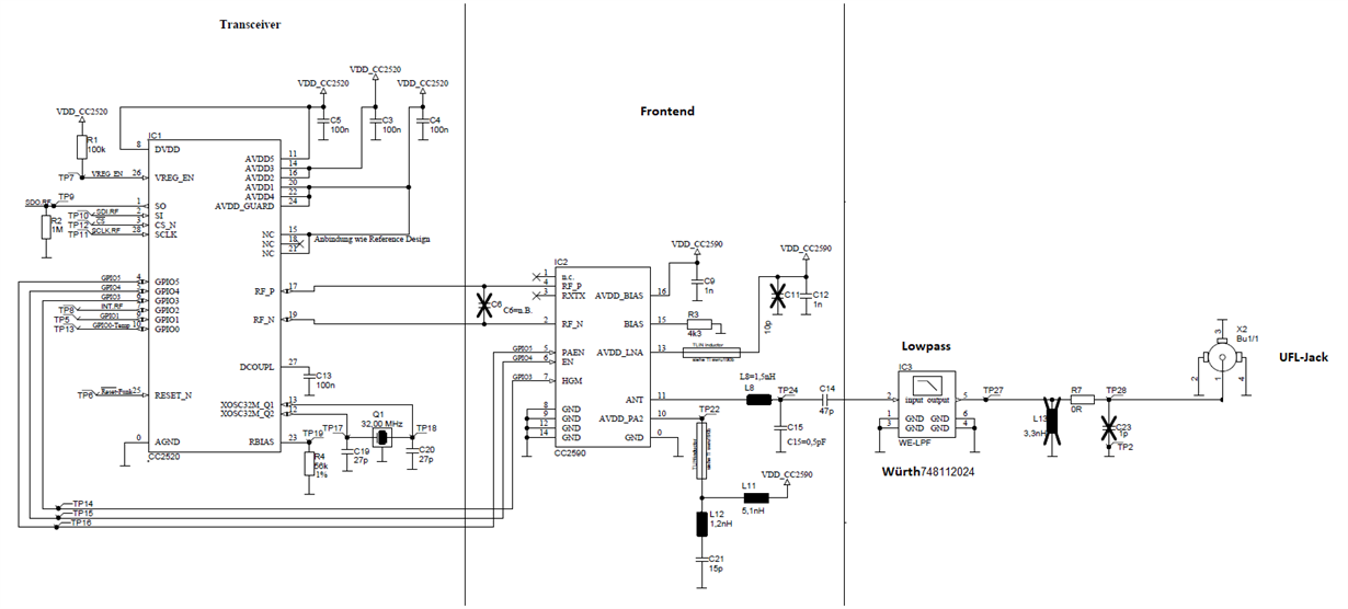
    The matching is from the Document CC2590EM Evaluation Module (SWRS080) we added a lowpass with 50Ohms. So it should be correct, right?? 

    The maximum conducted output-power is about 7dBm (power setting=F7). 

    Greetings Andreas


  • Hi Andreas,

    Yes, the matching I'm referring to is between the CC2950 and the UFL-Jack line. Notice your schematic has a 0 Ohm series resistor, and nothing in parallel. It's very likely that your RF trace out of the CC2590 is not matched to 50 ohms. To maximize your antenna's performance, you'll want to match it to 50 Ohms at 2.4 GHz. Adding a low-pass filter will not accomplish this. You will need to measure the network's impedance at the output of the CC2590, and add the appropriate capacitors/inductors at R7, C23 and/or L13 to match the antenna. My colleague Farrukh made this video that explains how.

    In general, I'd recommend following the reference design as closely as possible to maximize performance. In the reference design, we have 2 T filters between the CC2520 and the 2590's RF lines that you seem to be missing. I think this is also likely affecting your performance.

    Best,

    Nate

  • Hi Nate,

    thought the T-Filters between transceiver and frontend are only necessary when you use the older CC2591 with CC2520?

    In the datasheet of the CC2590 the typical application circuit with CC2520 shows no T-filters in between?

    Do we need them?

    Matching frontend to antenna:

    The RF-traces are designed to get 50Ohms (calculated with the actual  layerstack) (pcb-manufacturer told us the size of the traces to meet the impedance)

    Thought L8,C15 and C14 are there, to match the Frontend to 50Ohms? (Datasheet CC2590)

    The lowpass also has 50Ohms on both sides. And the UFL-Jack is connected direct to the 50Ohm-Spectrumanalyzer-port.

    Where is the mistake in my understanding? :-)

    Thanks 

    Andreas

  • T-filters: Yes you're correct. I see the reference design you're following now.

    I think the misunderstanding you're having about matching is that even when you do match the RF traces to 50 ohms (which is a great start!), the boards themselves may likely have a non-50 ohm trace due to the shape and size of the physical board after design. That's why we recommend leaving room for a matching network, to correct for that. 

    Just for the path leading out of the antenna, I'd recommend following the CC2541-2590 reference design topology. Use the LC filter comprised of L111, C111 and C112 exactly as is. Leave space for your matching components C113 and L112, and test (either measure or simulate) to find the best value for them. You may also consider putting a series element between C113 and L112 to make a Pi network for a better match. 

    As well, are the results you're showing simulated or measured?

  • Hi Nate,

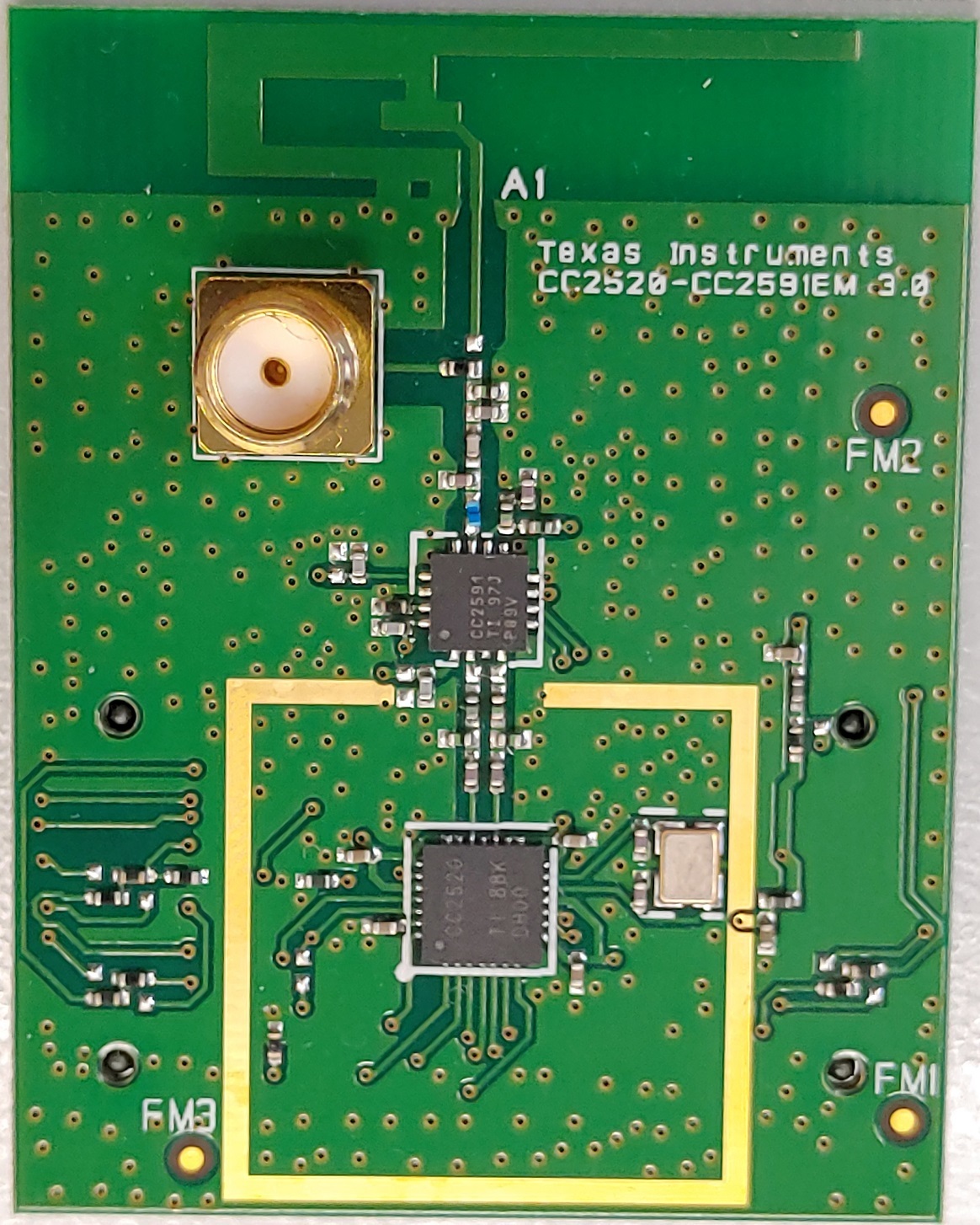
    took the EM -Board from Ti and changed the CC2591 to CC2590. 

    The spectrum is perfect and similiar with both ICs. (Except amplitude of course)

    if I remove the T-filters between CC2520 and CC2590 the spectrum is bad (grey) and similiar to the spectrum we have on our board (orange).

       (spectrum with T-Filters = green)

    Is the impedance of CC2520 and CC2590 not matching without those filters?

    Thanks 


  • Hi Andreas,

    I wouldn't necessarily call this an issue of matching as much as the effect of the bandpass filter. Glad you could find the issue!

    Best,

    Nate

  • Hi Nate,

    the issue isn't solved... we just got a little bit forward.   

    In the Datasheet of the CC2590 those components aren't necessary.

    Is it possible without those components?

    Greetings

  • I think so. Have you tried placing C6 on your design? The reference design you are following includes a capacitor between RF_P and RF_N.

  • Hi Nate,

    there is a cap called "C1" in the datasheet of the CC2590 . But there is no size mentionend.

    We tried a couple of values but didn`t improve the spectrum.

    What size of C1 is fitting?

    Do you have another refence design documentation without T-Filter?

    Thank you 

  • Hi Andreas,

    After consulting internally with our experts, our recommendation is to use the T-filters. You're seeing bad matching between the CC2520 and the CC2590, which is what the T-filters are designed to combat. I think they are omitted from the reference design because their value may vary depending on the board shape and design, but it seems clear that they're needed here based off the behavior you're seeing and all the reference designs available online.

    Best,

    Nate

  • Hi Nate,

    thanks for the information. Now we now where the problem is. :-)

    We have a series production with only this C6 mountable.

    Can you give us a value for this, that makes the best possible matching? 

    Greetings

  • Hi Andreas,

    Unfortunately, that's going to require some trial and error. Even in the best case, when we have a t/pi network set up, I have to measure the input impedance with the network analyzer, place components and do trial and error to match them. You have the additional complication of try to match 2 pairs of traces, and only doing so with a single parallel component between the two of them. I'm not sure if it will be possible for you to get a good match as a result, but I'd definitely suggest trying a few capacitors and inductors to see what the effect is.

    Best,

    Nate

  • Hi Nate,

    I'm sure you've got the impedance of both ICs...   

    CC2520 has about 69-j29

    CC2590 has about 200+0j     I guess.???

    now you can calculate what value would be best for matching?

    and thats where we start measuring.

    Greetings 

  • If those are listed values, then they can vary depending on your board and traces. I would highly recommend measuring on your board first, then testing to see if you can improve it. But, again, I think you're unlikely to generate strong improvements without being able to line series/shunt components for each path.

  • Hi Nate,

    I'm writing with you for some weeks now and wanted some help..   

    all that I get is a "that depends"  and "follow the application note"

    Now we know that the "Seamless Interface" and the application circuit of the CC2590-datasheet  is for advertising purposes only.

    and now I wanted just an estimate   and again I get an " that depends"

    guess we can close this topic.. 

    bye Andreas


  • Hi,

    I am afraid the process of matching the impedance is not straight forward in this case.

    The input and output impedances of CC2590 are mentioned in the thread below. You can use those to design the matching network.

    Please see this thread for guidance. e2e.ti.com/.../113384

    Regards,