


Other Parts Discussed in Thread: CC2564MODNEM
The Sample applications located in the folder
\TI\Connectivity\CC256X BT\CC256x STM32 Bluetopia SDK\v4.0.2.2\NoOS\STM3240G-EVAL\Samples
are for STM3240G-EVAL board. We are using STM32F4 Discovery. Moreover, we do not have the adapter board CC256XEM-STADAPT. We wired the connections from CC2564MODNEM to STM32 Discovery directly. The following sch shows the connections made.

First we evaluated the SPPDemo, it worked fine.
Then we tried AUDDemo, AVRCP part of this demo works, but unable to listen to the Audio on Discovery board.
For porting the AUDDemo code to STM32Discovery, we have made the following changes to the HALCFG.h, AUDIOCFG.h and AUDIO.C
- Console UART changed to UART2 (HALCFG.h)
- I2S config changed to I2S3 (AUDIOCFG.h)
- I2C init code and codec Reset pin config code is written in Initialize_AUDIO function (AUDIO.C)
HALCFG.h
-------------------------------------------------------------------------------------
#define CONSOLE_UART      2

#define CONSOLE_TXD_PORT  A
#define CONSOLE_TXD_PIN   2

#define CONSOLE_RXD_PORT  A
#define CONSOLE_RXD_PIN   3

#define HAL_LED_PORT      D
#define HAL_LED_PIN       13
------------------------------------------------------------
AUDIOCFG.h
------------------------------------------------------------
#define AUDIO_I2C 1

#define AUDIO_I2C_SDA_PORT B
#define AUDIO_I2C_SDA_PIN 9

#define AUDIO_I2C_SCL_PORT B
#define AUDIO_I2C_SCL_PIN 6

#define AUDIO_I2S 3

#define AUDIO_I2S_WS_PORT A
#define AUDIO_I2S_WS_PIN 4

#define AUDIO_I2S_SCK_PORT C
#define AUDIO_I2S_SCK_PIN 10

#define AUDIO_I2S_SDO_PORT C
#define AUDIO_I2S_SDO_PIN 12

#define AUDIO_I2S_MCK_PORT C
#define AUDIO_I2S_MCK_PIN 7

#define AUDIO_I2S_DMA_TX_NUMBER 1
#define AUDIO_I2S_DMA_TX_STREAM 5
#define AUDIO_I2S_DMA_TX_CHANNEL 0
------------------------------------------------------------
AUDIO.C
------------------------------------------------------------
int Initialize_AUDIO(unsigned long Frequency)
{
   int             ret_val;
   I2S_InitTypeDef I2SConfig;

   if(!AUDIO_Context.Initialized)
   {
      BTPS_MemInitialize(&AUDIO_Context, 0, sizeof(AUDIO_Context_t));

      AUDIO_Context.PlaybackState = psStopped;

      /* Configure the IO Expander for the CODEC's reset pin.           */
      //IOE_Config(); //Hari
      //---------------------------------------------------
      /* Enable the CODEC_I2C peripheral clock */
      RCC_APB1PeriphClockCmd(RCC_APB1Periph_I2C1, ENABLE);
      RCC_AHB1PeriphClockCmd(RCC_AHB1Periph_GPIOB, ENABLE);
      /* Reset IOE_I2C IP */
      RCC_APB1PeriphResetCmd(RCC_APB1Periph_I2C1, ENABLE);
      /* Release reset signal of IOE_I2C IP */
      RCC_APB1PeriphResetCmd(RCC_APB1Periph_I2C1, DISABLE);

      //---------------------------------------------------
      /* Enable the peripheral clocks.                                  */

      /* Connect PXx to I2C_SCL*/
      GPIO_PinAFConfig(GPIOB, GPIO_PinSource6, GPIO_AF_I2C1);
      /* Connect PXx to I2C_SDA*/
      GPIO_PinAFConfig(GPIOB, GPIO_PinSource9, GPIO_AF_I2C1);

          /* IOE_I2C SCL and SDA pins configuration */
      GPIO_InitTypeDef GPIO_InitStructure;
      GPIO_InitStructure.GPIO_Pin = GPIO_Pin_6;
      GPIO_InitStructure.GPIO_Mode = GPIO_Mode_AF;
      GPIO_InitStructure.GPIO_Speed = GPIO_Speed_50MHz;
      GPIO_InitStructure.GPIO_OType = GPIO_OType_OD;
      GPIO_InitStructure.GPIO_PuPd  = GPIO_PuPd_NOPULL;
      GPIO_Init(GPIOB, &GPIO_InitStructure);

      GPIO_InitStructure.GPIO_Pin = GPIO_Pin_9;
      GPIO_Init(GPIOB, &GPIO_InitStructure);

      /* Configure the GPIO.                                            */
      //---------------------------------------------------
      /* Enable Reset GPIO Clock */
      //GPIO_InitTypeDef GPIO_InitStructure;
      RCC_AHB1PeriphClockCmd(RCC_AHB1Periph_GPIOD,ENABLE);
      GPIO_InitStructure.GPIO_Pin = GPIO_Pin_4;
      GPIO_InitStructure.GPIO_Mode = GPIO_Mode_OUT;
      GPIO_InitStructure.GPIO_Speed = GPIO_Speed_50MHz;
      GPIO_InitStructure.GPIO_OType = GPIO_OType_PP;
      GPIO_InitStructure.GPIO_PuPd  = GPIO_PuPd_NOPULL;
      GPIO_Init(GPIOD, &GPIO_InitStructure);
      //---------------------------------------------------
//      GPIO_Init(AUDIO_I2C_SDA_GPIO_PORT, (GPIO_InitTypeDef *)&I2C_SDA_GpioConfiguration); //Hari
//      GPIO_Init(AUDIO_I2C_SCL_GPIO_PORT, (GPIO_InitTypeDef *)&I2C_SCL_GpioConfiguration); //Hari
      RCC_APB1PeriphClockCmd(AUDIO_I2S_RCC_PERIPH_CLK_BIT, ENABLE);
      RCC_AHB1PeriphClockCmd(AUDIO_I2S_WS_GPIO_AHB_BIT | AUDIO_I2S_SCK_GPIO_AHB_BIT | AUDIO_I2S_SDO_GPIO_AHB_BIT | AUDIO_I2S_MCK_GPIO_AHB_BIT, ENABLE);

      GPIO_Init(AUDIO_I2S_WS_GPIO_PORT,  (GPIO_InitTypeDef *)&I2S_WS_GpioConfiguration);
      GPIO_Init(AUDIO_I2S_SCK_GPIO_PORT, (GPIO_InitTypeDef *)&I2S_SCK_GpioConfiguration);
      GPIO_Init(AUDIO_I2S_SDO_GPIO_PORT, (GPIO_InitTypeDef *)&I2S_SDO_GpioConfiguration);
      GPIO_Init(AUDIO_I2S_MCK_GPIO_PORT, (GPIO_InitTypeDef *)&I2S_MCK_GpioConfiguration);

//      GPIO_PinAFConfig(AUDIO_I2C_SDA_GPIO_PORT, AUDIO_I2C_SDA_PIN, AUDIO_I2C_GPIO_AF);
//      GPIO_PinAFConfig(AUDIO_I2C_SCL_GPIO_PORT, AUDIO_I2C_SCL_PIN, AUDIO_I2C_GPIO_AF);

      GPIO_PinAFConfig(AUDIO_I2S_WS_GPIO_PORT,  AUDIO_I2S_WS_PIN,  AUDIO_I2S_GPIO_AF);
      GPIO_PinAFConfig(AUDIO_I2S_SCK_GPIO_PORT, AUDIO_I2S_SCK_PIN, AUDIO_I2S_GPIO_AF);
      GPIO_PinAFConfig(AUDIO_I2S_SDO_GPIO_PORT, AUDIO_I2S_SDO_PIN, AUDIO_I2S_GPIO_AF);
      GPIO_PinAFConfig(AUDIO_I2S_MCK_GPIO_PORT, AUDIO_I2S_MCK_PIN, AUDIO_I2S_GPIO_AF);

      /* Reset the CODEC.                                               */
      //IOE_WriteIOPin(AUDIO_RESET_PIN, BitReset); //Hari
      GPIO_WriteBit(GPIOD, GPIO_Pin_4, Bit_RESET);
      BTPS_Delay(50);
      //IOE_WriteIOPin(AUDIO_RESET_PIN, BitSet); //Hari
      GPIO_WriteBit(GPIOD, GPIO_Pin_4, Bit_SET);
      //Display(("\r\n CODEC RESET  succeded\r\n")); //Hari

      /* Initialize the I2C Interface.                                  */
      I2C_Cmd(I2C1, ENABLE);
      I2C_Init(I2C1, (I2C_InitTypeDef *)&I2C_Configuration);


      /* Keep Codec powered OFF                                         */
      if((ret_val = WriteRegister(0x02, 0x01)) == 0)
      {
         /* Set output to Headphone.                                    */
         if((ret_val = WriteRegister(0x04, DEFAULT_VOLUME)) == 0)
         {
            /* Clock configuration: Auto detection                      */
            if((ret_val = WriteRegister(0x05, 0x81)) == 0)
            {
               /* Set the Slave Mode and the audio standard to Phillips.*/
               if((ret_val = WriteRegister(0x06, 0x04)) == 0)
               {
                  /* Set the Master volume                              */
                  if((ret_val = AUDIO_Set_Volume(AUDIO_DEFAULT_VOLUME)) == 0)
                  {
                     /* Power on the Codec                              */
                     ret_val = WriteRegister(0x02, 0x9E);
                  }
               }
            }
         }
      }

      if(!ret_val)
      {
         /* These configurations are done to reduce the time needed for */
         /* the Codec to power off.  If these configurations are        */
         /* removed, then a long delay should be added between powering */
         /* off the Codec and switching off the I2S peripheral MCLK     */
         /* clock (which is the operating clock for Codec).  If this    */
         /* delay is not inserted, then the codec will not shut down    */
         /* propoerly and it results in high noise after shut down.     */

         /* Disable the analog soft ramp                                */
         if((ret_val = WriteRegister(0x0A, 0x00)) == 0)
         {
            /* Disable the digital soft ramp                            */
            if((ret_val = WriteRegister(0x0E, 0x04)) == 0)
            {
               /* Disable the limiter attack level                      */
               if((ret_val = WriteRegister(0x27, 0x00)) == 0)
               {
                  /* Adjust Bass and Treble levels                      */
                  if((ret_val = WriteRegister(0x1F, 0x0F)) == 0)
                  {
                     /* Adjust PCM volume level                         */
                     if((ret_val = WriteRegister(0x1A, 0x0A)) == 0)
                     {
                        Display(("\r\nAdjust PCM volume level  succeded\r\n"));
                        ret_val = WriteRegister(0x1B, 0x0A);
                  }
               }
            }
         }
      }
      }

      if(!ret_val)
      {
         /* Configure the I2S peripheral                                */
         I2S_Cmd(AUDIO_I2S_BASE, DISABLE);

         /* Configure the initial PLL values for the sake of I2S_Init.  */
         RCC->CFGR       |= RCC_CFGR_I2SSRC;
         RCC->CR         &= ~((uint32_t)RCC_CR_PLLI2SON);
         RCC->CFGR       &= ~RCC_CFGR_I2SSRC;
         RCC->PLLI2SCFGR  = FrequencyConfiguration[0].PLL_I2S;
         RCC->CR         |= ((uint32_t)RCC_CR_PLLI2SON);
         while(!(RCC->CR & RCC_CR_PLLI2SRDY));

         /* Initialize the I2S interface.                               */
         BTPS_MemCopy(&I2SConfig, &I2S_Configuration, sizeof(I2S_InitTypeDef));
         I2SConfig.I2S_AudioFreq = Frequency;
         I2S_Init(AUDIO_I2S_BASE, (I2S_InitTypeDef *)&I2S_Configuration);
         if((ret_val = SetFrequency(Frequency)) == 0)
         {Display(("\r\n 517 AUDIO\r\n"));
            I2S_Cmd(AUDIO_I2S_BASE, ENABLE);

            NVIC_SetPriority(AUDIO_I2S_IRQ, AUDIO_INTERRUPT_PRIORITY);
            NVIC_EnableIRQ(AUDIO_I2S_IRQ);
         }
      }

      if(ret_val)
      {
         /* there was an error in the initialization, disable the I2S      */
         /* interface.                                                     */
         I2S_Cmd(AUDIO_I2S_BASE, DISABLE);
         SPI_I2S_ITConfig(AUDIO_I2S_BASE, SPI_I2S_IT_TXE, DISABLE);
         SPI_I2S_DeInit(AUDIO_I2S_BASE);
      }
      else
      {
         AUDIO_Context.Initialized = TRUE;
         AUDIO_Context.PlaybackState = psPlaying;
      }
   }
   else
   {
      ret_val = AUDIO_Pause_Resume_CODEC();
   }

   return(ret_val);
}
------------------------------------------------------------
The following screenshot shows the output on console uart when connected to smartphone bluetooth. Also Log file is here

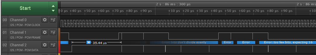
Also the Logic analyzer screenshot for I2S Lines
Full modified project source is here for download.
The CODEC I2C part works fine, only I2S part seems to be a problem.
Thank you in advance.
BR
Reddy
