This thread has been locked.

If you have a related question, please click the "Ask a related question" button in the top right corner. The newly created question will be automatically linked to this question.

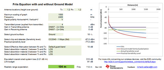
Excel sheet to estimate range for Indoor and Outdoor

Other Parts Discussed in Thread: CC2640R2F, CC2540, CC2538, CC2564, CC1190, CC1120, CC-ANTENNA-DK2, CC1310, CC2640

Hi,

The attached excel sheet helps to estimate a practical range estimation for indoor and outdoor radio links.

The outdoor is based upon Line-of-Sight (LOS). For the indoor estimation, construction materials can be selected that are between the Tx and Rx unit. The greater the attenuation of the combined material between the Tx and Rx unit, the shorter the distance.

This has been used a lot in TI seminars and is a helpful tool for calculating a realistic and conservative range expectation.

The latest version is available at: http://www.ti.com/tool/rf-range-estimator

Latest version (1.17) has been updated to include:

  • CC2640R2F - 500 kbps (BLE)
  • CC2640R2F - 125 kbps (BLE)

Any feedback is welcomed.

Regards, Richard


  • Hey,

    This is cool stuff!! Once I did a test with two CC2540EM (using dipole antennas) and I got a range about 260m outdoors on an open field. Your tool approximates 104m, am I missing something or did I just got lucky when doing the measurement? :) Picture attached.

    Edit: After looking more closely on the graph and knowing that CC2540 has -93dBm in sensitivity (High-Gain mode), I see that my measurement is backed up by Friis equation. Really useful tool here!!

  • Hi Joakim,

    Thanks for the feedback.

    Good to hear that the LOS results correlate.

    This tool helps a lot especially when discussing indoor range and the impact of having a "dry wall" or "concrete" wall between the Tx and Rx units.  

  • Hello Joakim,

    I appreciate your work..

    but can you tell me is your tool support cc2538 chip also ? becoz i am using cc2538 and zstack HA 1.20 so how can i use your tool ?


    thanks & regards,

    Maneesh

  • CC2538 is included in the Rev1_03 version.

    Regards, Richard

  • How does this work? I tried entering the same inputs as Joakim, but I got #N/A as a result in the write protected cells

    Edit: I got it working by using "." as a decimal point instead of ",".

    What is the typical gain for iOS devices and how could I enter in such a value? How do I select different absorbtion materials?

  • There is no typical gain value for an iOS device since this depends on the specific design of the antenna. For a typical gain value, I would keep this at 0 dB for 2.4 GHz.

    Regards, Richard

  • Richard,

    Your spreadsheet is very, very helpful.  Would you mind sharing the source of your wall energy absorption numbers?

    Thank you,

    --Jamie

  • Hi Jamie,

    The source of the energy absorption numbers is from a report from the U.S. National Institute of Standards and Technology (NIST).

    Regards, Richard

  • Ver 1.07 supports CC13xx and CC26xx.


    Regards, Richard
  • Documentation on how to use this excel range calculation can be found at: www.ti.com/.../swra479

    Regards, Richard
  • Are there plans to add support for CC2564xxxxx parts?
  • Hi Marc,

    I can add the CC2564x parts in the drop down list in the next version.

    For time being, just choose a radio /data rate setting that correlates to the sensitivity level specified by the CC2564x.

    Regards, Richard

  • Ver 1.08: updated with support for CC2564, CC31xx and CC32xx and added link to documentation
  • Your spreadsheet is very, very helpful.
  • and I believe this video demos the longest CC1120+cc1190 RF link distance. Thumbs up RIchard!
    www.youtube.com/watch

  • Thanks for the sheet. What would be the ideal channel model for a urban/semi urban scenario for IEEE 802.15.4g 2/4 FSK ?. 2Ray or Hata model?
  • The post is a good one, lots of things one can learn here
  • I did some line-of-sight tests between the TI CC2540 in a Panasonic PAN1720 module and an iPhone 6 and logged the reported RSSI on the iPhone and on the CC2540 as a function of distance.  The RSSI on the CC2540 in standard receiver sensitivity would clip at around -35 dBm but the iPhone would not clip so had usable results for very close proximity.  The following formula for the CC2540 fit very well with a coefficient of determination of 0.994 (the iPhone has a roughly similar formula but didn't fit quite as well at 0.989) where both devices were about 4 feet (3.3 m) above the ground.

    RSSI = -22.9 * LOG10(distance in feet) - 38.7

    and I found that the connection would drop or be very unstable when the RSSI got to -85 and especially below -90 which is roughly the noise level (from Wi-Fi diagnostics) and the receiver sensitivity is -87.  This translates into a (barely) usable distance of around 100 feet though -87 would give 130 feet.  Your spreadsheet with no guard band gives 156 meters or 512 feet which seems overly optimistic while using the 20 dB "Guard band without Antenna Diversity" may be OK for a very reliable link at 21 meters (69 feet).

    Your RSSI vs. distance was roughly  the following:

    1 meter --> -40 RSSI

    3 meter --> -50 RSSI

    10 meter --> -60 RSSI

    25 meter --> -70 RSSI (ground model vertical polarization)

    100 meter --> -80 RSSI

    200 meter --> -90 RSSI

    which if I convert to feet to compare to my formula I get the following as a fit for yours:

    RSSI = -21.2 * LOG10(distance in feet) - 28.8

    So it looks like your rolloff with distance is roughly similar but your offset overestimates the RSSI as being roughly 10 dBm higher for any given distance.  Any thoughts as to why there is this difference?

  • Hi,

    I'm an antenna engineer (amongst other things) and I've designed & measured *lots* of antennas at 2.4GHz (=Bluetooth & WiFi). Usually in mobile devices you aim for low directivity, so that the link doesn't depend on the orientation of the devices. In practice, it's usually between 2 to 5 dBi so that is how much gain variation you can expect just by turning the device(s) to different orientations. Normally there are one or two nulls in the radiation pattern too, but these are typically quite narrow angle.

    Gain is directivity + antenna efficiency, and the latter varies a lot depending on the antenna type - a good dipole can be -0.5dB and a poorly designed internal antenna -10dB. The efficiency represents losses in the antenna's internal structure and so doesn't depend on orientation.

    Add to that the effect of holding the device in your hand, and that again can make a big difference if you happen to grab it just on top of the antenna (and without disassembling the phone, you usually don't know where it is. In a small gadget it's actually less of a problem because the whole device is about 1/2 wavelength long and so the whole PCB acts as the antenna).

    So, what I'm saying is that it varies a lot and much of it is beyond the control of the designer. Using something between -3 and -6 dB for gain is probably more realistic than 0 dB in most cases, but always remember that the free-space range represents the best case scenario!

    cheers
    -Mikko
  • Hi Mikko,

    Good input and totally agree that the gain can never really be specified in a general format. The excel sheet is mainly used to show a more realistic range expectation compared to the standard Friis formula. A specific range can never be guaranteed by anyone but this is more a tool to help assist engineers to predict a more realistic range.

    When we measure customer products that have integrated antennas in the chamber, then we enter the final values directly into the excel sheet and the range accuracy is even better. There are many parameters which effect the range and these cannot all be specified in a easy manner.

    Have updated the version to Rev 1.11. This supports the new Long Range Modes from CC13xx and improved the accuracy of predicted range a little bit more.

    Regards,
    Richard
  • Latest version (Rev1.12) updated with:

    - Checklist for debugging in the event of poor range
    - Better overview of realistic antenna gains for various frequencies for "hand held" devices
    - More precise range estimation
  • Latest version (1.14) has been updated to include:

    • selected chip's blocking parameter (+/- 10 MHz) and how this effects range with an unwanted interference / jammer.
    • environment noise floor parameter since this is becoming an important factor in several countries. 
    • Mean Effective Gain of antennas (measurements from CC-Antenna-DK2) 

    Any feedback is welcomed.

    Regards, Richard

  • Hi,

    Updated to v1.15 and fixed a small bug. The existing figures in the excel sheet correlate to the 20 km range test performed on the CC1310 LaunchPad.

    Regards,
    Richard
  • Latest version (1.16) has been updated to include:

    • Changed guard band to link margin 
    • Custom frequency, sensitivity and blocking level can be entered
  • Latest version (1.17) has been updated to include:

    CC2640R2F - 500 kbps (BLE)
    CC2640R2F - 125 kbps (BLE)
  • Hello Joakim,

    I also appreciate your work. Thank you very much for the Excel sheet.

  • Thank you very much for your Excel sheet. However I have a question.

    Is it really accurate? How do I estimase the correct range of BLE?
    I used CC2640+Antenna PCB (referenced from TI design) to check in the real environment (Don't have the wall). I used iPhone 7 to scan the RSSI of device.
    <1 m: -40 to -50 RSSI
    <3 m: -50 to -70 RSSI
    <10 m: -70 to - 80 RSSI
    >15 m: very weak

    I maked many projects on BLE from CC254x to CC26xx. But BLE distance is <20 m. It is too short compared to the realistic range expectation.
  • Why nobody considering polarization of the antenna for calculating linkbudget .
  • It's going to depend on the antenna, but for the standard antenna as used in the CC2540 USB Evaluation module kit and in the PAN1720 module, I measured the free space RSSI and found the following (regression determined) formula to be reasonably accurate for +0 dBm output power: RSSI = -22.9 * log10(distance in feet) -38.7

    Using your distances I get

    1 meter as -50.5

    3 meter as -61.4

    10 meter as -73.4

    I was generally able to connect if the RSSI was somewhat above the noise level, usually OK to around -80 dBm (sometimes to -85 dBm, but not reliably) so around 19.5 meters.

    So basically I get similar results to what you are getting even though you are using the newer CC2640 chip.  That's the way it goes with BLE unless you use a better antenna.  You can easily get 10 to 15 dBm higher with a better antenna which would get you to 53 to 88 meters, but they are much larger than the chip antenna.  You can also use +4 dBm output power and higher receiver sensitivity for a little better range.

  • I really agree with you. The range of ble is the important issue. Because it will be shorter when it is used in home with wall, door...
  • Richard,

    great to find this updated tool - thank you.

    Regards, Bernd