


I'm generating a PWM signal with with 60 cycles frequency (CPU runs @ 48MHz) and a match value of 27 cycles.
I'm generating events on timer used for PWM on both positive and negative edges.
These two events triggers an UDMA transfer from memory to a GPIO DOUT_N register corresponding to PIN N.
Data transferred is a sequence of bytes {1, 0, 1, 0, 1, ...}. Consequently, on PIN N I should have an image of PWM signal.
Here is captured signal (PWM on channel 0, signal on PIN N resulting from UDMA transfer to GPIO DOUT_N register on channel 2) :
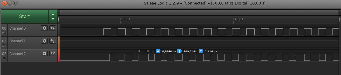
I need to understand two things :
- first rising edge on channel 2 is shifted of ~500ns (~25 cycles). How can we precisely explain this shift? How can we quantify it? How can I decrease it? This shift is kept during all transfer, so it is not because of transfer start, is seems to be needed duration for 1 byte transfer from memory to DOUT.
- PWM is a clean signal with a constant High duration of 0.68µs and a 1.27µs period. Signal on Channel 2 should be an image of this PWM signal. But On Channel 2 we can see : period is between : 1.46 and 1.12 µs, and High duration can vary, here in given measure I have a 0.91µs High duration with a period of 1.416µs and in next period I have an High duration of 0.60µs and a period of 1.14µs. How can we explain these changes? How can I get a precise image of my PWM signal?
After I did another test with two PWM, on first PWM labelled Timer A - HIGH on image Negative edges events are triggered by timer
on second PWM labelled Timer B - Low on image Negative and Positive edges events are triggered by timer
Timer A event trigger an UDMA transfer from memory to a GPIO DOUT_N register corresponding to PIN N, here is transferred data :
{ 0, 0, 0, 0, 0, 0};
Timer B events trigger an UDMA transfer from memory to a GPIO DOUT_N register corresponding to PIN N, here is transferred data :
{1, 0, 1, 0, 1, 0, 1, 0, 1, 0, 1, 0}
Consequently, on PIN N I should have an image of PWM labelled Timer B.

On channel 2 first period High level duration ~ Timer B High level duration. But after, Low level duration = 1.002µs, where it should be Timer B Low level duration = 0.73µs.
If we remember triggered events on Timer A and Timer B :
- at t0, we get a Rising edge event on Timer B => an UDMA transfer of byte 1 is written to DOUT_N => rising edge on Channel 2 HIGH level after ~500ns (UDMA transfer duration)
- t0 + 540ns after we get a Falling edge event on Timer B => an UDMA transfer of byte 0 is written to DOUT_N => falling edge on Channel 2 after ~500ns (UDMA transfer duration)
- at t0 + 540ns + 150 ns we get a Falling edge event on Timer B => 0 byte must be transferred using UDMA to DOUT_N, but previous UDMA transfer is not yet finished, it will end up at t1 = t0 + 540ns + 500ns => current transfer is queued, it will be handled at t1 and it will end at t2 = t0 + 1540ns. This transfer has no effect on Channel 2 (already to low level),
- at t0 + 1.27µs (PWM period), we get a Rising edge event on Timer B => 1 byte must be transferred using UDMA to DOUT_N => but previous transfer is not yet finished => current transfer is queued, it will be handled at t2 and will finish at t3 = t0 + 2040ns (can be confirmed on given capture)
From these steps, on first period, Low level duration = t3 - (t0 + 540 + 500) ~ 1µs = duration for 2 UDMA transfer. Because of UDMA transfer duration we cannot get a precise image of Timer B...
So once again, how can we speed up UDMA transfer duration? How can we quantify it?
Lah
