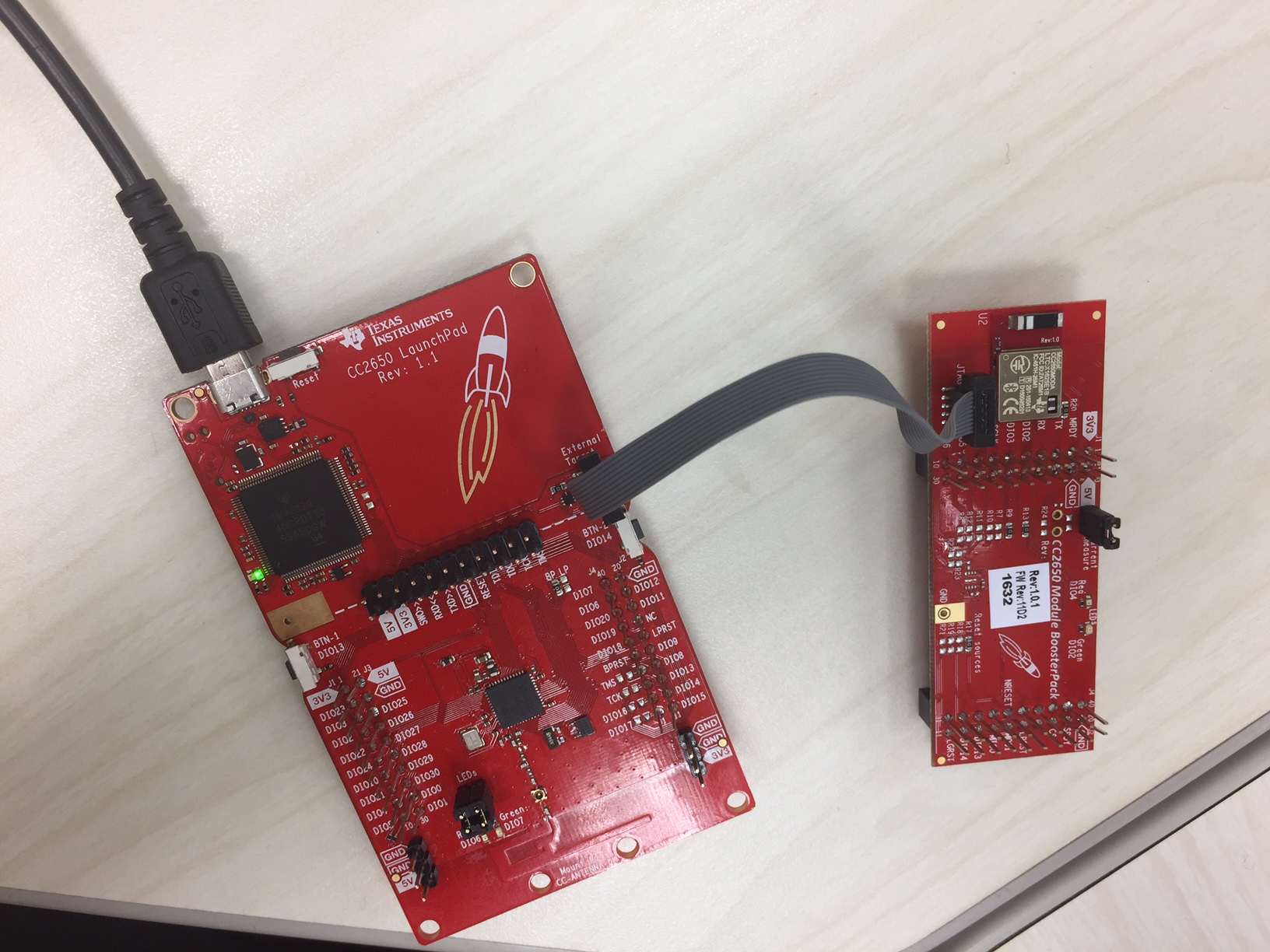
I am trying to debug an custom board with CC2650MODA mount using the CC26550 Launchpad.
I have several questions regarding the procedure.
1. The CC2650 Launchpad schematics suggests using P7 to debug an external device, P5 to debug on board CC2650 with external debugger. I identify two 10 pin headers on the board, which must be P5 and P7; however, I don't know which one is which. I think the one on the top is P7 and the one on the bottom is P5. Is this correct?
The CC2650 Launchpad schematics does not go in detail how the 10 pins of P7 has to be connected to the external device. 4 [pin 1, 3, 5, and 7] is connected to the ground, other 6 goes somewhere.
2. I don't know which of the 10 physical pins corresponds to which pin the schematics. Does it go top row [pin 1, 3, 5, 7, 9] and bottom row [pin 2, 4, 6, 8, 10]? How is it laid out?
3. Do I want to directly connect the 10 pin header to the CC2650MODA pins I have on my custom board? It seems like there is a direct connection between P5 and the CC2650 on board. I am wondering if this is what I want to replicate for P7 and the custom board.