This thread has been locked.

If you have a related question, please click the "Ask a related question" button in the top right corner. The newly created question will be automatically linked to this question.

CCS/CC2650MODA: CC2650MODA

Part Number: CC2650MODA
Other Parts Discussed in Thread: CC2650, SYSBIOS, BLE-STACK

Tool/software: Code Composer Studio

Hello,

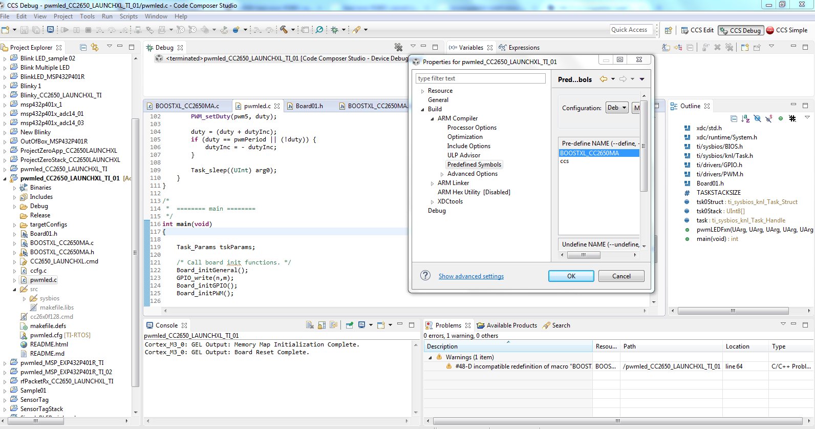
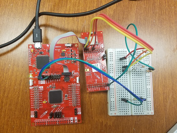
I have been working on CC2650Moda  and trying to use GPIO pins to turn ON/OFF the leds off-board. The example I am working with is in Code Composer Studio, TI-RTOS CC2650 Launchpad. And the GPIO-write(pin,on/off) is not working. Also, I enabled the pin using this command:

const PIN_Config BoardGpioInitTable[] = {
 IOID_6      | PIN_GPIO_OUTPUT_EN | PIN_GPIO_HIGH | PIN_PUSHPULL | PIN_DRVSTR_MAX,

I am not sure what is the reason that I cannot control leds with GPIO-write command and I would appreciate if someone help me to how to turn ON/OFF off-board leds.

Thanks in advance for your time,

Farinaz

This is the pwm code that I am using:

 *  ======== pwmled.c ========
 */
/* XDCtools Header files */
#include <xdc/std.h>
#include <xdc/runtime/System.h>

/* BIOS Header files */
#include <ti/sysbios/BIOS.h>
#include <ti/sysbios/knl/Task.h>

/* TI-RTOS Header files */
#include <ti/drivers/GPIO.h>
#include <ti/drivers/PWM.h>

/* Example/Board Header files */
#include "Board.h"

#include <ti/drivers/GPIO.h>            // has been added this line

#define TASKSTACKSIZE   512

#include "driverlib/gpio.h"                // has been added this line

Task_Struct tsk0Struct;
UInt16 tsk0Stack[TASKSTACKSIZE];
Task_Handle task;


/*
 *  ======== pwmLEDFxn ========
 *  Task periodically increments the PWM duty for the on board LED.
 */
Void pwmLEDFxn(UArg arg0, UArg arg1, UArg arg2, UArg arg3)
{
    PWM_Handle pwm1;
    PWM_Handle pwm2;
    PWM_Handle pwm3;
    PWM_Handle pwm4;
    PWM_Handle pwm5;

    PWM_Params params;
    uint16_t   pwmPeriod = 30000;      // Period and duty in microseconds
    uint16_t   duty = 80;
    uint16_t   dutyInc = 10;

    PWM_Params_init(&params);
    params.dutyUnits = PWM_DUTY_US;
    params.dutyValue = 0;
    params.periodUnits = PWM_PERIOD_US;
    params.periodValue = pwmPeriod;
    pwm1 = PWM_open(Board_PWM0, &params);
    pwm2 = PWM_open(Board_PWM1, &params);
    pwm3 = PWM_open(Board_PWM2, &params);
    pwm4 = PWM_open(Board_PWM3, &params);
    pwm5 = PWM_open(Board_PWM4, &params);


    if (pwm1 == NULL) {
        System_abort("Board_PWM0 did not open");
    }
    PWM_start(pwm1);
    PWM_start(pwm2);
    PWM_start(pwm3);
    PWM_start(pwm4);
    PWM_start(pwm5);

    /* Loop forever incrementing the PWM duty */
    while (1) {
        PWM_setDuty(pwm1, duty);
        PWM_setDuty(pwm2, duty);
        PWM_setDuty(pwm3, duty);
        PWM_setDuty(pwm4, duty);
        PWM_setDuty(pwm5, duty);

        duty = (duty + dutyInc);
        if (duty == pwmPeriod || (!duty)) {
            dutyInc = - dutyInc;
        }

        Task_sleep((UInt) arg0);
    }
}

   /*======== main ========*/

int main(void)
{
    Task_Params tskParams;

    /* Call board init functions.*/
    Board_initGeneral();
    Board_initGPIO();
    Board_initPWM();


     /*Construct LED Task thread*/
    Task_Params_init(&tskParams);
    tskParams.stackSize = TASKSTACKSIZE;
    tskParams.stack = &tsk0Stack;
    tskParams.arg0 = 50;
    Task_construct(&tsk0Struct, (Task_FuncPtr)pwmLEDFxn, &tskParams, NULL);

    /* Obtain instance handle*/
    task = Task_handle(&tsk0Struct);

 
    /* Turn on user LED*/
    GPIO_write(IOID_6, 1);
    GPIO_write(IOID_3, 0;
    GPIO_write(IOID_5, 1);


    //System_printf("Starting the example\nSystem provider is set to SysMin. "
    //              "Halt the target to view any SysMin contents in ROV.\n");

     /*SysMin will only print to the console when you call flush or exit*/

    System_flush();
    /* Start BIOS*/
    BIOS_start();

    return (0);
}

  • Hi,

    Did you change the board define of the project? Go to Project -> Properties -> Build -> ARM Compiler -> Advanced Options -> Predefined Symbols and change CC2650LAUNCHXL to BOOSTXL_CC2650MA .
  • Hi Marie,

    Thank you for the reply. I followed the steps but it did not work.  In Predefined Symbols section I have Pre-define NAME which was ccs and I added BOOSTXL_CC2650MA to it. And Configuration is Debug(Active).

    The command  GPIO_write(IOID_2, Board_LED_ON) is still not working.

    Regards,

    Farinaz

  • Hi Farinaz,

    What's the name of the project you started with?

  • The project that I am using is example in CCS which is TI-RTOS for CC26XX  ----- Developments Tools ------ CC2650-LAUNCHXL ------ Driver Example ------- PWM Example ------ PWM LED . I know this example is for CC2650 launchpad but I changed all the maping pins to CC2650MA.

    This is some part of edited header file.

    /* Discrete outputs */
    #define Board_RLED                  IOID_4
    #define Board_GLED                  IOID_2
    #define Board_LED_ON                1
    #define Board_LED_OFF               0
    //#define LED_ON                        1     // has been added
    //#define LED_OFF                        0     // has been added

    /* Discrete inputs */
    #define Board_BTN1                  PIN_UNASSIGNED
    #define Board_BTN2                  PIN_UNASSIGNED

    /* UART Board */
    #define Board_UART_RX               IOID_1          /* RXD  */
    #define Board_UART_TX               IOID_0          /* TXD  */
    #define Board_UART_CTS              PIN_UNASSIGNED         /* CTS  */
    #define Board_UART_RTS              PIN_UNASSIGNED       /* RTS */

    /* SPI Board */
    #define Board_SPI0_MISO             IOID_12          /* RF1.20 */
    #define Board_SPI0_MOSI             IOID_11          /* RF1.18 */
    #define Board_SPI0_CLK              IOID_10         /* RF1.16 */
    #define Board_SPI0_CSN              PIN_UNASSIGNED
    #define Board_SPI1_MISO             PIN_UNASSIGNED
    #define Board_SPI1_MOSI             PIN_UNASSIGNED
    #define Board_SPI1_CLK              PIN_UNASSIGNED
    #define Board_SPI1_CSN              PIN_UNASSIGNED

    /* I2C */
    #define Board_I2C0_SCL0             IOID_4
    #define Board_I2C0_SDA0             IOID_5

    /* SPI */
    #define Board_SPI_FLASH_CS          IOID_9
    #define Board_FLASH_CS_ON           0
    #define Board_FLASH_CS_OFF          1

    /* Booster pack generic */
    #define Board_DIO0                  IOID_0
    #define Board_DIO1_RFSW             IOID_1
    #define Board_DIO12                 IOID_12
    #define Board_DIO15                 IOID_15
    #define Board_DIO16_TDO             IOID_5
    #define Board_DIO17_TDI             IOID_6
    #define Board_DIO21                 IOID_21
    #define Board_DIO22                 IOID_22


    #define Board_DIO23_ANALOG          IOID_23
    #define Board_DIO24_ANALOG          IOID_24
    #define Board_DIO25_ANALOG          IOID_25
    #define Board_DIO26_ANALOG          IOID_26
    #define Board_DIO27_ANALOG          IOID_27
    #define Board_DIO28_ANALOG          IOID_28
    #define Board_DIO29_ANALOG          IOID_29
    #define Board_DIO30_ANALOG          IOID_30

    /* Booster pack LCD (430BOOST - Sharp96 Rev 1.1) */
    #define Board_LCD_CS                IOID_24 // SPI chip select
    #define Board_LCD_EXTCOMIN          IOID_12 // External COM inversion
    #define Board_LCD_ENABLE            IOID_22 // LCD enable
    #define Board_LCD_POWER             IOID_23 // LCD power control
    #define Board_LCD_CS_ON             1
    #define Board_LCD_CS_OFF            0

    /* PWM outputs */
    #define Board_PWMPIN0                       Board_RLED
    #define Board_PWMPIN1                       Board_GLED
    #define Board_PWMPIN2                       IOID_3
    #define Board_PWMPIN3                       IOID_5
    #define Board_PWMPIN4                         IOID_6
    #define Board_PWMPIN5                       PIN_UNASSIGNED
    #define Board_PWMPIN6                       PIN_UNASSIGNED
    #define Board_PWMPIN7                       PIN_UNASSIGNED

    Marie H. thanks for your help!

    Regards,

    Farinaz

  • Hi Farinaz,

    Can you try deleting Board.h, CC2650_LAUNCHXL.c and CC2650_LAUNCHXL.h from the project and then add Board.h, BOOSTXL_CC2650MA.c and BOOSTXL_CC2650MA.h from the location C:\ti\tirtos_cc13xx_cc26xx_2_20_01_08\products\tidrivers_cc13xx_cc26xx_2_20_01_10\packages\ti\boards\BOOSTXL_CC2650MA into your project?
  • Hi Marie,

    Thanks for your help. I deleted c and h files of CC2650_LAUNCH and added BOOSTXL_CC2650 but still it does not work. Also, I receive 1warning in CCS and that is : incompatible redefinition of macro "BOOSTXL_CC2650MA". Also, I edited predefined-sysmbols. My CCS page can be seeing in the figure below:

    Furthermore, to clarify the setup that I have , I am using MSP432P401R LaunchPad as a debugger XDS110 USB Debug Probe and CC2650 Module Booster Pack. These two are connected with JTAG cable.The purpose of using CC2650 is using Bluetooth and programming that for the custom made PCB which my friend and I designed it.

    Thanks in advance for your time and consideration.

    Regards,

    Farinaz

  • Hi Farinaz,

    Are you powering the CC2650MODA?

    You can do this by mounting it on the launchpad (read the bottom paragraph of this page: dev.ti.com/.../BOOSTXL-CC2650MA.html ).

    Or you can connect the corresponding pins without mounting it.
  • Hi Marie,

    Thanks for the reply.

    Yes, I am powering CC2650MODA. I am using M3.

    I understand that I can use MSP431P401 LaunchPad and CC2650MA together. But my plan is using CC2650 standalone and program it alone by using XDS110 USB cable.

    The PWM code that I am using is:

    * ======== pwmled.c ========
    */
    /* XDCtools Header files */
    #include <xdc/std.h>
    #include <xdc/runtime/System.h>

    /* BIOS Header files */
    #include <ti/sysbios/BIOS.h>
    #include <ti/sysbios/knl/Task.h>

    /* TI-RTOS Header files */
    #include <ti/drivers/GPIO.h>
    #include <ti/drivers/PWM.h>

    /* Example/Board Header files */
    #include "Board.h"
    #include "GPIOCC26XX.h" (I added this line to see if it helps, but it didn't work)


    #define TASKSTACKSIZE 512

    Task_Struct tsk0Struct;
    UInt8 tsk0Stack[TASKSTACKSIZE];
    Task_Handle task;

    /*
    * ======== pwmLEDFxn ========
    * Task periodically increments the PWM duty for the on board LED.
    */

    Void pwmLEDFxn(UArg arg0, UArg arg1, UArg arg2, UArg arg3, UArg arg4)
    {
    PWM_Handle pwm1;
    PWM_Handle pwm2;
    PWM_Handle pwm3;
    PWM_Handle pwm4;
    PWM_Handle pwm5;

    PWM_Params params;
    uint16_t pwmPeriod = 30000; // Period and duty in microseconds
    uint16_t duty = 80;
    uint16_t dutyInc = 10;

    PWM_Params_init(&params);
    params.dutyUnits = PWM_DUTY_US;
    params.dutyValue = 0;
    params.periodUnits = PWM_PERIOD_US;
    params.periodValue = pwmPeriod;
    pwm1 = PWM_open(Board_PWM0, &params);
    pwm2 = PWM_open(Board_PWM1, &params);
    pwm3 = PWM_open(Board_PWM2, &params);
    pwm4 = PWM_open(Board_PWM3, &params);
    pwm5 = PWM_open(Board_PWM4, &params);

    if (pwm1 == NULL) {
    System_abort("Board_PWM0 did not open");
    }
    PWM_start(pwm1);
    PWM_start(pwm2);
    PWM_start(pwm3);
    PWM_start(pwm4);
    PWM_start(pwm5);

    // Loop forever incrementing the PWM duty
    while (1) {
    PWM_setDuty(pwm1, duty);
    PWM_setDuty(pwm2, duty);
    PWM_setDuty(pwm3, duty);
    PWM_setDuty(pwm4, duty);
    PWM_setDuty(pwm5, duty);

    duty = (duty + dutyInc);
    if (duty == pwmPeriod || (!duty)) {
    dutyInc = - dutyInc;
    }

    Task_sleep((UInt) arg0);
    }
    }


    /*
    * ======== main ========
    */

    int main(void)
    {
    Task_Params tskParams;

    /* Call board init functions. */
    Board_initGeneral();
    Board_initGPIO();
    Board_initPWM();


    /* Construct LED Task thread */
    Task_Params_init(&tskParams);
    tskParams.stackSize = TASKSTACKSIZE;
    tskParams.stack = &tsk0Stack;
    tskParams.arg0 = 50;
    Task_construct(&tsk0Struct, (Task_FuncPtr)pwmLEDFxn, &tskParams, NULL);

    /* Obtain instance handle */
    task = Task_handle(&tsk0Struct);

    /* Turn on user LED */
    GPIO_write(IOID_3, Board_LED_OFF);
    GPIO_write(IOID_5, 0);
    GPIO_write(IOID_6, Board_LED_OFF);

    System_printf("Starting the example\nSystem provider is set to SysMin. "
    "Halt the target to view any SysMin contents in ROV.\n");

    /* SysMin will only print to the console when you call flush or exit */
    System_flush();

    /* Start BIOS */
    BIOS_start();

    return (0);
    }


    And it does work without any error, but it doesn't perform GPIO_write command. I need that command to be able to turn leds ON/OFF. This section is not working:

    /* Turn on user LED */
    GPIO_write(IOID_3, Board_LED_OFF);
    GPIO_write(IOID_5, 0);
    GPIO_write(IOID_6, Board_LED_OFF);

    Thanks in advance for your time and consideration!
    Regards,
    Farinaz

  • Hi Farinaz,

    Looking at the board from the BoosterPack (C:\ti\simplelink\ble_sdk_2_02_01_18\src\boards\BOOSTXL_CC2650MA, assuming you are using BLE-Stack 2.2.1). I see that:

    #define     GPIO_toggle(n)
    
    #define     GPIO_write(n,m)

    are defined as dead code, thus they will compile to nothing. Instead of using these macros, since you are using TI-RTOS, I would recommend using the PIN driver.


    To get you started with the PIN driver I would recommend doing the following, remove the GPIO_* related #include statements and replace them with:


    #include <ti/drivers/PIN.h>
    
    #include <ti/drivers/pin/PINCC26XX.h>

    Make a pin table structure (this can be global in your main file for now) :


    PIN_Config ledPinTable[] = {
    
        IOID_6 | PIN_GPIO_OUTPUT_EN | PIN_GPIO_HIGH | PIN_PUSHPULL | PIN_DRVSTR_MAX,
    
        IOID_6 | PIN_GPIO_OUTPUT_EN | PIN_GPIO_LOW  | PIN_PUSHPULL | PIN_DRVSTR_MAX,
    
        PIN_TERMINATE
    
    };

    Open the Pins (do this at init)

        ledPinHandle = PIN_open(&ledPinState, ledPinTable);
    
        if(!ledPinHandle) {
    
            System_abort("Error initializing board LED pins\n");
    
        }

    Then modify the PIN state using the following API

    PIN_setOutputValue(ledPinHandle, Board_LED0, Board_LED_OFF );


    You can see more examples of the PIN driver in (C:\ti\tirtos_cc13xx_cc26xx_2_20_01_08\examples\TI\CC2650_LAUNCHXL\pinInterrupt) (again assuming the TI-RTOS used by BLE-Stack 2.2.1).